
![]()
Mechanical
Mechanical drawings are drawings that are made with precision instruments. Engineers and technicians prepare these designs with strict technical requirements in mind; every drawing accurately captures the specifications of each part: dimensions, quantities of material, angle tolerances, installation instructions, and so on. As such, mechanical drawings consist of straight, orthogonal lines and geometric shapes. The elements in mechanical drawings have perfectly uniform measurements such as 90-degree angles and curves with a uniform radius. Contrast this with organic, freehand shapes. The Scan2CAD mechanical vectorization setting looks out for straight lines, right angles and arcs.
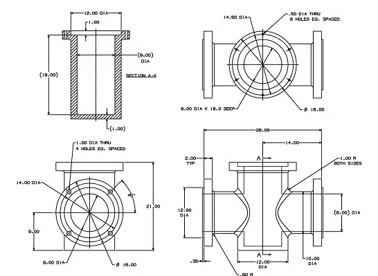
Note the straight lines, right angles and uniform shapes
Electrical
Electrical schematic diagrams are made up of straight lines joined together at right angles. The electrical vectorization setting differs from the mechanical one in its treatment of overlapping lines. The intersections in electrical diagrams denote where the wires form an electrical connection. If there’s a connection, electricity passes through both wires and they aren’t insulated from each other. Contrast this with site plans, in which intersecting lines are simply two separate lines crossing over or overlapping with each other.
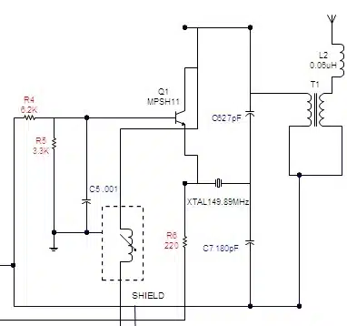
Lots of overlapping lines and intersections in electrical drawings
Contour Map
Contour maps are designed to capture information about the Earth’s elevation, such as the steepness of slopes and the positions of hills in a landscape. Since the Earth isn’t made of straight lines, contour maps aren’t too. In other contexts, contour maps represent the boundary of a shape. When this setting is chosen, Scan2CAD converts the shape into Bezier curves or splines. Scan2CAD can also retain the different colours of the contour map, so you can always differentiate green grass from blue rivers!
Lots of curvy lines in contour maps!
Architectural
Architectural floor plans are scale diagrams of a building. Since they reflect the shape and dimensions of buildings, they tend to be made up of horizontal and vertical lines. Scan2CAD needs to keep these lines as straight as possible. The architectural vectorization setting applies processes like corner sharpening (to create 90-degree angles), gap jumping (to fill in gaps and create unbroken straight lines) and corner snapping (to make two vectors meet nicely at a corner).
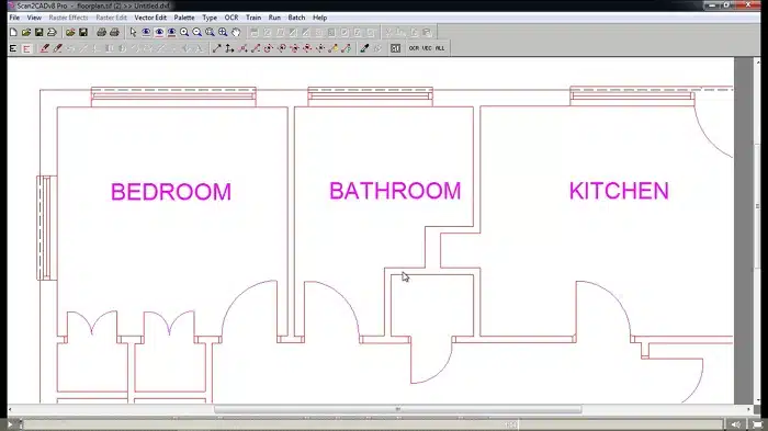
Like buildings, architectural floor plans are made up of straight, orthogonal lines
Site Plan
Site plans differ from architectural floor plans in that they illustrate the actual landscape of the parcel of land. This includes the contours and the topography of the land, as well as important landscape elements (such as a large oak tree, sewer lines, trails and so on). When treating site plans, Scan2CAD is careful not to create orthogonal lines.
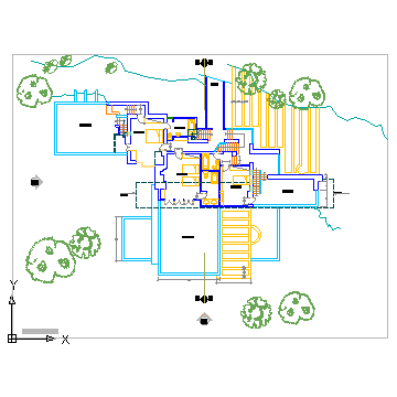
Site plans contain more organic shapes, as they portray the landscape (trees, trails, water lines and all!)
CNC Profile
A vector drawing prepared for CNC profiling has to meet the requirements of the CNC process. For example, the shapes in the drawing must be uniform and “machinable”, so that a machine can characterize it using formulas. The vector shapes in the drawing define the actual cut paths that the machine will follow – so you have to be careful not to create unwanted lines in the drawing. Scan2CAD optimizes for these requirements by reducing the number of lines and node points where possible.
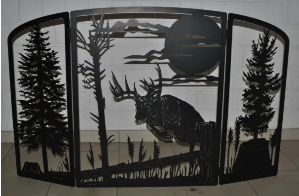
This screen was created with CNC
Outline
As its name suggests, the outline setting outlines solid areas of black or colour. It’s the go-to setting if you’re looking to trace the edges of your drawing.

Here’s a raster image where we’d use the Outline setting
Picture/Photo
As photographs can be so varied, it’s difficult to have a predefined set of parameters that can be applied generally. Therefore, Scan2CAD allows you to define the conversion settings every time you vectorize an image. You can choose which elements are identified, such as circles, regular polygons, beziers, and more. There’s a preview window too so that you can experiment with a variety of settings until you get your desired output. The picture/photo setting can be surprisingly powerful. You can use it to create clean outlines of very detailed elements — just by defining “non solid” in the conversion settings window.
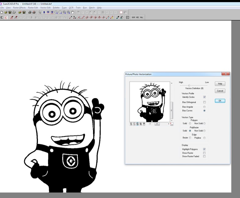
We’ve converted a picture of a Minion into a CNC-ready vector
Want to learn more? You can find lots more tips and advice on our regularly updated blog, and in the Scan2CAD User Manual, which has a section on Vectorization Settings.
