
AutoCAD’s model space is somewhat infinite. If you zoom out, for example, you will notice that the software will continuously regenerate the model. So, any object you will have previously created will disappear from view. Of course, this feature is advantageous as it enables users to work on projects of unprecedented scale. However, it equally creates a problem as far as locating exact points on existing objects is concerned. How so? While you can zoom into, say, a line, you will observe that picking the exact location of one of the ends is practically impossible. You may think that you have selected the end, but you will notice this is not the case upon zooming in further. Fortunately, AutoCAD object snaps and object snap tracking exist to help in such cases.
Table of Contents
What is AutoCAD Object Snap?
Object snap, which can be shortened to Osnap, is a feature that enables you to easily find and set the exact/precise locations of points on geometric objects in AutoCAD. Introduced by Autodesk back in 1984 with the rollout of AutoCAD Version 2.0 or Release 5, which allows snapping to reference points of existing objects. These points, which are denoted by a green marker, could be anything from the midpoint and endpoint of a line to the center of a circle and quadrant or tangent of an ellipse or circle.
The green marker, you will observe, is shaped in the form of a triangle, circle, or square, with the shape varying based on the snap it is marking. For instance, a square indicates the endpoint of a line, the circle shows the center of a circle, and the triangle specifies the midpoint of a line. The marker, which is part of a set of tools known as AutoSnap™, visually confirms that AutoCAD Osnap is in effect. In all, the AutoSnap tools include:
- Marker: It visually displays the location of the object snap when the cursor hovers over or near that point
- Tooltip: It shows the name of the object snap, i.e., whether it is a midpoint, endpoint, center, quadrant, and so on
- Magnet: It attracts and claps the cursor onto the nearest AutoCAD osnap location
- Aperture box: It surrounds the crosshairs (a crosshair is the cursor in AutoCAD denoted by two intersecting lines, in what resembles a plus sign) and defines the area within which osnaps are evaluated.
AutoCAD Object Snap Modes
As stated above, the Osnap feature snaps to various reference points. These points are also referred to as object snap modes. Below is a list of the various modes/points you can use:
a) Midpoint
It snaps to the midpoint of a geometric object such as a line, xline, polyline segment, arc, ellipse, spline, or edge of a 3D object.

Midpoint Osnap
b) Endpoint
It snaps to the closest corner or endpoint of an object, such as a polyline segment, spline, line, arc, or 3D object.
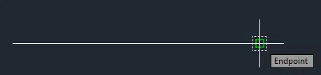
Endpoint Osnap
c) Center
It snaps to the center of a circle, arc, ellipse, or elliptical arc.
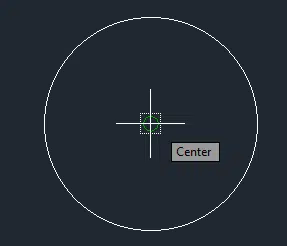
Center Osnap
d) Geometric Center
It snaps to the geometric center of a polyline or 2D spline.
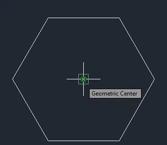
Geometric Center Osnap
e) Quadrant
It snaps to the quadrant of a circle, arc, ellipse, or elliptical arc.
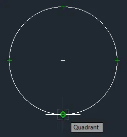
Quadrant Osnap
f) Tangent
The tangent osnap mode snaps to the tangent of a circle, arc, ellipse, elliptical arc, or spline.
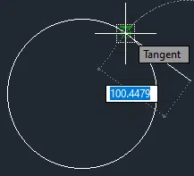
Tangent Osnap
g) Perpendicular
It snaps to a point that is perpendicular to an object, such as a line, multiline, polyline, spline, xline, 3D solid, circle, ellipse, arc, elliptical arc, ray, or region.
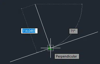
Perpendicular Osnap
h) Parallel
The parallel snap mode forces a line segment, polyline segment, ray, or xline to be parallel to another linear object in the drawing.
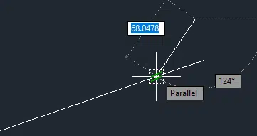
Parallel Osnap Marker
i) Intersection
It snaps to the intersection of objects such as lines, polylines, xlines, splines, arcs, circles, and ellipses.
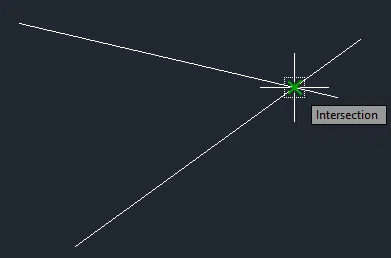
Intersection Osnap
j) Apparent Intersect
It snaps to the visual intersection of two objects that do not intersect in a 3D space but may appear to intersect in the current view.
k) Extension
It enables a temporary extension arc or line to appear when you hover the cursor over the endpoints of the objects. This allows you to specify points on the extended line or arc.
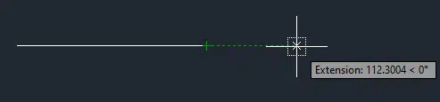
Extension Osnap
l) Node
The node object snap mode snaps to a point object, dimension text origin, or dimension definition point.
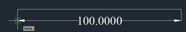
Node Osnap
m) Insertion
The insertion snap mode snaps to the insertion point of objects such as blocks, texts, or attributes.
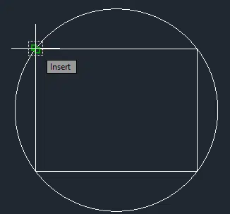
Insertion Osnap
n) Nearest
It snaps to the nearest point on an object, such as a line, spline, xline, polyline, arc, circle, ellipse, elliptical arc, point, or ray.
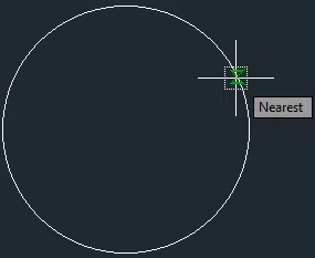
Nearest Osnap
What is Object Snap Tracking in AutoCAD?
When turned on, the AutoCAD object snap tracking tracks the cursor along vertical (90º) and horizontal (180º) alignments as well as alignments that form an angle of 30º, 60º, 120º, or 150º from a horizontal reference line that crosses the object snap point. This tool, therefore, makes it easy to create objects that conform to specific angular parameters; the alternative entails fiddling with the mouse until you arrive at a certain angle.
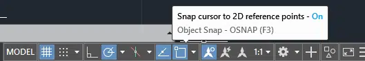
To turn the object snap tracking on and off, simply press the F11 function key or click the Object Snap Tracking – AUTOSNAP button on the status bar.
AutoCAD Object Snap Tracking – AUTOSNAP Button
How to Use AutoCAD Osnap Feature
To enjoy the convenience that comes with this feature, you must turn on the option in AutoCAD. Do note that you can choose to have Osnap activated throughout the period you will be using AutoCAD. In such a case, you will be using what is known as the Running Object Snap. If you do not wish to have the feature running, you can turn off the Running Object Snap and instead activate the tool as and when you need to use it. In this section, we will detail how to activate either of these two options. We shall also detail how to cycle through various object snap modes.
How to Turn on and off Object Snap in AutoCAD as and when Needed
To turn on (and off) the AutoCAD object snap tool as and when needed, follow the procedure below:
- Click on the icon of the drawing tool, i.e., a line, circle, arc, and so on, to initiate the process of creating the geometric object
- When prompted to Specify first point, hold down the Shift key and right-click any area within the model space.
- Choose the object snap mode you intend to use from the object snap menu that pops up
- Hover your cursor over the desired location of the object snap
AutoCAD will automatically display a marker and tooltip, indicating the exact location of the Osnap point. The software will also lock the cursor onto this location. - Hit the right mouse button to set the location as the first point and subsequently create the geometric object
This approach requires you to activate the AutoCAD object snap every time you want to use the feature. This is because whenever you use steps 2 to 4 above to create an object snap upon receiving the prompt, the Osnap stays active until you specify that point. To put it simply, it is deactivated once you complete step 5. Thus, if you want the AutoCAD object snap feature to be available continuously, you have to activate the Running Object Snap option.
How to Turn on and off Running Object Snap Option in AutoCAD
If you want to draw a line from the midpoint of a rectangle to the center of a tiny circle located within the rectangle, the AutoCAD running object snap feature makes everything a breeze. This is because it eliminates the need to use the Shift key or open a secondary menu. Instead, all you have to do is to move your cursor over the region on the geometric object you perceive to be the location of the point, and AutoCAD will automatically display the exact location using a green marker.
But how do you turn on (and off) the Running Object Snap feature in AutoCAD? There are two approaches: using one of the function keys, F3, or the OSNAP button on the status bar. Pressing the F3 key once activates the Running Object Snap, meaning that if you want to turn it off, you just have to press the F3 key once more. Do note that the software informs you every time you switch the Running Object Snap on (and off) by turning on (and off) the OSNAP button’s blue background color.
Alternatively, you can turn on the Running Object Snap feature by clicking the OSNAP button on the status bar. Activating this tool switches on the background color, while deactivating it switches the color off.
AutoCAD Object Snap Button
Compared to the first approach – the F3 function key – this second option enables you to further activate the AutoCAD object snap modes you intend to use as you create your drawing. To achieve this, simply follow these steps:
- Press the drop-down arrow beside the OSNAP button
- On the menu that pops up, choose the appropriate modes.
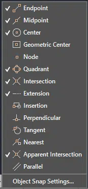
Object Snap Modes
- Alternatively, you can also click the Object Snap Settings option to open the Drafting Settings dialog box. You can use this dialog box to again activate or deactivate the Running Object Snap modes.
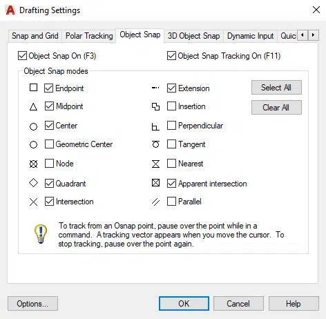
Drafting Settings Dialog Box
How to Cycle Through AutoCAD Object Snap Modes
Additionally, you can use the Tab key to cycle through the available AutoCAD Osnaps, especially if they are located on the same geometric object. For example, if you hover over a line and subsequently hit the Tab key, firstly, AutoCAD will highlight the line. Next, it will display a different object snap every time you press the Tab key.
Conclusion
The AutoCAD Osnap or object snap is a handy feature that promotes convenience. It enables you to use specific points of an existing geometric object, such as a line, circle, arc, polyline, and ellipse, to draw additional objects. By turning this feature on, you can use the midpoint of a line or the center of a circle as the first point. Additionally, you can turn on object snap tracking for even better results. This is because this tracking tool allows you to create geometric objects that align with specific angles, i.e., 30º, 60º, 90º, 120º, 150º, or 180º from a horizontal reference line.
