
AutoCAD’s model space is an unlimited drawing space that enables you to draw anything from a map or house plan to a 2D section of a machine part. However, the somewhat infinite space can pose a challenge when it comes to positioning the starting point of the first line of the drawing at an exact point relative to the model space’s coordinates. You are also likely to experience this challenge if you have used AutoCAD to create a map and wish to locate a specific point that you can use as a reference within the extensive map. Fortunately, the software has simplified this process through the AutoCAD POINT command.
Table of Contents
What is AutoCAD Point?
Abbreviated as PO, POINT is a command that enables you to create multiple markers (also known as point objects) that you can use as a reference. This command makes it easier to snap objects to a precise point in an otherwise blank area. As we have extensively explained in our guide to the AutoCAD object snap feature, you can only snap to particular points in existing geometric objects such as lines, arcs, circles, and so on. Thus, by creating a marker in an otherwise blank space, the AutoCAD POINT command establishes a reference point to which you can snap objects as you commence the drawing process.
How to Create Points in AutoCAD
To create a point in AutoCAD, follow these steps:
- Type POINT or PO and hit Enter
You can type this command arbitrarily, as AutoCAD automatically creates a text box next to the cursor that you can then reference as you type. Alternatively, you can type the command in the Command Line. Regardless of the approach you take, the effect will be the same.
Alternatively, you can click the Home ribbon tab > the drop-down arrow in the Draw panel > Multiple Points button. - Specify a point
You can specify a point by left-clicking on a particular area within the model space. However, this is less accurate, especially if you want to position the drawing relative to AutoCAD’s coordinate system. Therefore, we recommend defining the location based on the coordinates for increased accuracy and precise positioning. For instance, if you want to point to be located at a distance of 200mm from both the x and y-axis, simply type 200 (to represent the location on the x-axis) > press Enter > type 200 (to represent the location on the y-axis) > press Enter > type 0 to represent the location on the z-axis (this defines the elevation of the point) > press Enter. AutoCAD will automatically create this point.
You will notice that you can use the Osnaps tool to snap an object to this point, provided this tool is turned on. By default, the newly created AutoCAD point is selectable. This means that you can easily delete it should the need arise. However, you will also observe that the point is displayed as a tiny point. Its small size makes the point easy to miss, especially if you zoom out. You might even struggle to locate it once you start zooming in. Fortunately, AutoCAD allows you to change both the shape and size of the point.
How to Change the Point Type in AutoCAD?
Also known as the point style, the point type refers to the shape of the marker that denotes the location of the point. There are three ways to change the point style or point type in AutoCAD:
How to Change the Point Type using the PDMODE System Variable Command
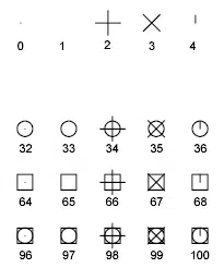
PDMODE Values in AutoCAD (source)
The PDMODE is used to control how AutoCAD displays the point objects. It is based on a number system, whereby each number denotes a specific shape that is drawn around or through a point. For instance, 0 specifies that a point is displayed, while 1 instructs AutoCAD not to display any shape around a point. Similarly, a value of 2 displays the + sign, whereas a value of 3 will display the x sign.
However, for the PDMODE command to work, you must ensure that you input a valid value that the system recognizes. For instance, 31 or 37 return an invalid response, while 32 and 36 change the shape of the point. This is because the system recognizes the latter group of numbers, but not the former. Beside is a list of the values you can use and the shape they represent.
To use the PDMODE command, follow the steps below:
- Create an AutoCAD point (refer to the procedure in the section above)
- Type PDMODE and press enter
- Type one of the values shown in the image above and press enter
How to Change the Point Type using the PTYPE Command
AutoCAD also allows you to change the point style using a graphical-based approach. To do this, follow the procedure below:
- Type PTYPE and hit Enter or click on the Home ribbon tab > the Utilities ribbon panel > Point Style option
This opens the AutoCAD Point Style dialog box
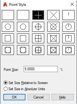
Point Style Dialog Box in AutoCAD
- Select your desired shape from the list.

How to Change the Point Style by Using Custom Blocks
You can also change the point style by manually creating custom shapes and blocks. Unfortunately, AutoCAD does not allow you to create custom point styles and then add them to its database of styles, similar to how you can create and add custom Hatch patterns in AutoCAD. So, when it comes to AutoCAD points, you must manually move the custom block to the location of the point. Here is how to do this:
- Create an AutoCAD point using the PO command
- Create a block by following these steps:
- Create the shape you want to use as a point style
- On the Home ribbon tab, click on the Block ribbon panel and select the Create option
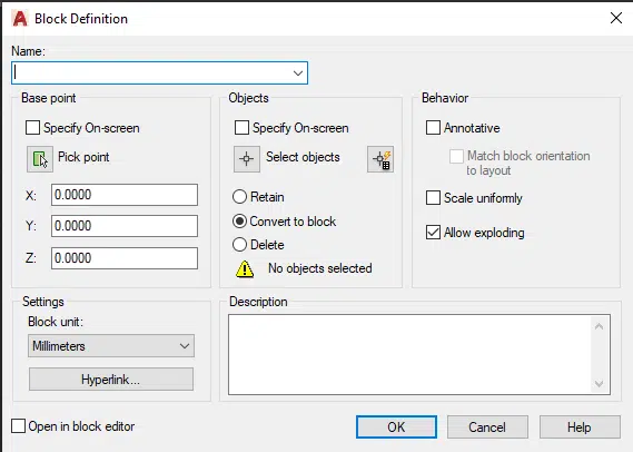
- On the Block Definition dialog box that pops up, enter the name of the block and select the objects you want AutoCAD to convert to a block
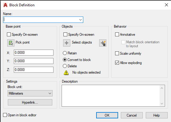
Block Definition Dialog Box in AutoCAD
- Click OK.
- Insert the block into your drawing/model space
- Click on the Move command in the Modify ribbon panel of the Home tab
- When prompted to select objects, click on the block you have inserted in step 3 above and press Enter
- Specify the base point
Ensure you have toggled on the AutoCAD Object Snap feature for the best possible results. Additionally, ensure you have checked either the Center or Midpoint options in the Object Snap Settings. This ensures accuracy when selecting the base point, especially because you should select the center or midpoint of the shape or line as your base point. - Choose the AutoCAD point as the second point
Again, the Osnap feature is handy in ensuring you select the exact location. The block will snap into place and will now act as a new marker for the point.
How to Change Point Size in AutoCAD
The AutoCAD Point Style dialog box also allows you to change the size of the points. Simply follow the procedure below:
- Type PTYPE and hit Enter
This command opens the AutoCAD Point Style dialog box - Set the point size by typing into the number box within the dialog box
- Specify whether you want to Set size relative to screen or Set size in absolute units by checking one of the two options
If you set the size relative to the screen, the point size will increase as you zoom out and decrease as you zoom in. (In case the size does not change automatically, use the REGEN command to update the parameter and attribute text size.) On the other hand, if you set the point size in absolute units, the size will remain unchanged regardless of whether you have zoomed in or out. Instead, it will be based on the size set in step 2 above.
How to Measure the Coordinates of a Point in AutoCAD?
Say you have received an AutoCAD drawing from your colleague. Upon scrutiny, you discover that the drawing has multiple points you are supposed to use as references but are not labeled to notify you of their distance from the origin. Instead of seeking clarification from your colleague on these measurements, you can use the AutoCAD ID point feature. Here are the steps to follow:
- Click on the Home ribbon tab > Utilities ribbon panel > ID Point option
- Specify a point by clicking on one of the points whose coordinates you want to measure
AutoCAD temporarily displays the coordinates, representing the distance from both the origin along the x and y axes.
Conclusion
This article covers everything there is to know about AutoCAD points, from how to create a point to how to change the point style and size. Additionally, we have detailed how you can create custom point styles using the block creation process. Finally, we have detailed how you can use the ID Point tool to measure the coordinates of an AutoCAD point. We, therefore, hope you have gained knowledge that will help you in your design journey using the popular AutoCAD software.
