Product development, the process of taking a product from the idea or concept stage through market release, involves collaboration among teams. While a collaborative approach does govern virtually all steps of the process, it is perhaps more clearly seen during the ideation and design phases, where team members exchange ideas with one another. Here, software applications that aid in computer-aided design (CAD), computer-aided manufacturing (CAM), and computer-aided engineering (CAE) play a central role in helping design professionals visualize their ideas.
In some cases, however, these designers may need to change their CAD software, perhaps upon identifying an application whose use can result in better outcomes. They may also need to incorporate suppliers’, customers’, or subcontractors’ data into their designs, with this data generated by different software. Ordinarily, such circumstances will likely lead to interoperability problems that may delay design, especially if the data was saved using native file formats. While such file formats can be translated to conform to the requirements of the software used to open them, this can often result in translation errors that require the allocation of resources to repair. Additionally, the translation errors can cause downstream problems such as corrupted data or interferences. Fortunately, such problems can be avoided if you use neutral CAD file formats.
Table of Contents
What are 3D CAD File Formats?
A 3D CAD file format stores information pertaining to a 3D model created using a particular CAD software. This information, which is stored as either plain text (ASCII) or binary, includes:
- Geometric data: It describes whether the model is a wireframe, surface, solid, 2D drawing, part, or assembly
- Appearance: It relates to the textures and colors of the model
- Scene: It details the position of light relative to objects as well as the location of peripheral objects
- Animation: It defines the nature of the movement of the 3D model
- Metadata: It relates to non-graphical properties such as the system, part or detail numbers, author or creator of the drawing, file path on the computer or network storage, and revision number
- Design intent data: It includes history trees (common in parametric modeling), rules and guidelines, and formulas
- Application data: It relates to such data as geometric dimensioning and tolerancing (GD&T), numerical control tool paths, assembly structure, and process planning
Combined, this information provides clarity. It is a source of accurate design data for any party that intends to use the model or drawing stored using that particular file format. However, not every 3D CAD file format stores all this data. Against this backdrop, there are three main types of CAD file formats:
- Native 3D CAD file formats
- Geometric modeling kernel formats
- Neutral 3D CAD file formats
1. What are Native 3D CAD File Formats?
You can think of native file formats as an avenue for software developers to create a walled garden. In order to lock in users to their own ecosystems, these companies develop proprietary formats, which can only be read or written by their software or licensed applications.
Thus, a native file format is any proprietary file type created by a 3D CAD software solution developer. It stores as much of the model data as possible to retain the model’s important details. Thus, when using a native 3D file format on its native software, you will see that it captures details such as appearance, design intent, and geometry. The software also generates application data. For instance, by undertaking GD&T, the software uses a symbolic language to define permissible deviations of feature geometry, annotating drawings and designs for downstream processes. This data is then stored as application data.
The native file formats are generated using proprietary authoring systems that define the structure of the file. Take the example of a DWG (drawing) file native to the AutoCAD software. DWG is made up of sections and subsections. DWG is created using an authoring system known as RealDWG. Essentially, for a software developer to create an application with the capability to read or write DWG, they must incorporate the RealDWG toolkit into their application. And to get a hold of the toolkit, they must obtain a license. Examples of native 3D CAD file formats are summarized in the table below:
|
Native File Format |
File Extension |
Software |
|
Model |
.model |
|
|
SLDPRT and SLDASM |
.sldprt and .sldasm |
|
|
BLEND |
.blend |
Blender |
|
IPT and IAM |
.ipt and .iam |
|
|
Bundle |
.bdl |
|
|
SketchUp |
.skp |
|
|
ArchiCAD Solo Projects |
.pln |
|
|
RVT |
.rvt |
|
|
Designfile |
.dgn |
|
|
3D Studio |
.3ds |
Autodesk 3ds Max |
|
Filmbox |
.fbx |
Autodesk FBX |
Drawbacks of Native 3D CAD File Formats
The above example points to the proprietary nature of native CAD file formats, which means they are costly to license and use. Additionally, these file formats present compatibility problems. If the software is not licensed, it cannot read or write the native file format. To get around this problem, translation tools exist. But unfortunately, this also gives rise to a number of other problems. As stated earlier, translation causes errors, some of which require repairs on an ongoing basis. These translation errors can also cause downstream problems, such as corrupted data in the product development pipeline. To solve these issues, you can use neutral 3D CAD file formats. And as we will detail later, you can also convert a native file format to a neutral one.
2. What are Geometric Modeling Kernel Formats
While there are several geometric modeling kernel formats, the CAD space is dominated by two popular ones – ACIS and Parasolid. These formats are designed to facilitate the seamless transfer of information between multiple software applications. They are beneficial because they do not result in any loss of data. This is due to their use of mathematical formulas to describe shapes. And they work best when used to exchange data between software that are built on top of the same kernel. For instance, you can easily and losslessly transfer data between software that use the Parasolid kernel, i.e., similarly built applications, as opposed to two applications that support different kernels, say, Parasolid and ACIS.
|
Geometric Modeling Kernel Format |
File Extension |
|
Parasolid |
.x_t and .x_b |
|
ACIS |
.sat and .sab |
|
Open CASCADE |
.brep |
|
OpenNURBS |
.3dm |
|
GRANITE |
.g |
3. What are Neutral 3D CAD File Formats?
A neutral CAD file format is one that is not proprietary. This means it can be read or written by any software that supports it without licensing. For this reason, such a file format is not associated with any software and is meant for general usage. Neutral 3D CAD file formats, therefore, greatly facilitate collaboration and interoperability. They are used when design professionals want to transfer CAD data from one software to another or when they want to import data created by vendors or suppliers.
The interoperability aspect is enhanced because neutral 3D CAD file formats do not require a special license or the activation of a special module. However, this does not mean that all of them are open source – some formats were unconditionally made available to other software despite having been created by CAD software companies. For instance, Jupiter Tessellation was developed by HP and Engineering Animation as part of the Direct Model toolkit. However, Siemens Digital Industries Software acquired Engineering Animation, bringing the format under its control. Furthermore, in the early 2010s, JT received ISO standardization (ISO 14306:2012) and is currently used as a standard exchange format.
Examples of neutral file formats include:
|
Neutral File Format |
File Extension |
|
STEP |
.stp and .step |
|
Stereolithography |
.stl |
|
VRML |
.vrml |
|
IGES |
.igs and .iges |
|
DXF |
.dxf |
|
COLLADA |
.dae |
|
3D PDF |
|
|
Extensible 3D |
.x3d |
|
Wavefront OBJ |
.obj |
|
International Foundation Class |
.ifc |
|
Jupiter Tessellation |
.jt |
While Parasolid is a neutral file format, it has to be licensed
Drawbacks of Neutral File Formats
However, neutral file formats have their drawbacks: they do not contain as much design or model data as their native counterparts. This is because they only store the basic information representing the model and disregard other data that they consider unnecessary.
How to Convert Native 3D CAD Files to Neutral 3D CAD File Formats
Using neutral CAD file formats is a no-brainer if your workflow mainly entails collaborating with other professionals. If you want to transition from your previous usage of native formats to neutral ones and enjoy the interoperability benefits that abound, you can always perform a conversion.
The process of converting one file format to another is known as CAD data translation. Here, the goal is to retain as much information as possible from the original model. And this depends on three main factors:
- The information supported by the neutral CAD file format: The translation process should ensure the correct transfer of geometry, surface, appearance, and scene data. Thus, successful conversion involves choosing a neutral file format that supports all this information.
- Standardization of the file format: A standardized file has a known structure that software vendors can easily implement. Selecting such a file format eliminates translation errors to a certain extent.
- The software’s implementation of a neutral file format: software vendors often implement the same file format differently. This can mean that data that was saved by the exporting application may be ignored by the importing software, resulting in errors.
To convert a native CAD file format to a neutral one, you can use CAD modeling software that supports both formats or a third-party solution. That said, it is worth pointing out that some software developers, such as Autodesk (with its Inventor product), have striven to ensure their applications can read virtually any CAD file without translation. This way, they support 3D CAD interoperability.
Criteria for Choosing the Best Neutral CAD File Formats
It is worth pointing out that the neutral file formats differ in various ways. For instance, some retail scene data, while others do not. Other formats store color and texture data, while others do not. Thus, when analyzed through the lens of the information retained – and, therefore, their capabilities – neutral file formats can be scored, resulting in a list of the top neutral 3D CAD file formats. At the same time, some file formats are compatible with all major 3D CAD software, while others cannot be read or written by certain CAD programs. These differences form the criteria for creating the best neutral file formats list.
For the sake of clarity, the criteria are based on the following characteristics:
1. Level of Detail (LOD)
The level of detail describes the amount of information a model contains. A good neutral CAD file format stores as much information as possible. From geometric and metadata to appearance and scene data. Formats that store more data rank higher on the list of the best neutral CAD file formats, while those that store less data rank lower.
2. Complexity
Furthermore, a format’s ability to seamlessly represent complex assemblies and parts is an added advantage. This ability is hinged on the use of hierarchies. It is worth pointing out that formats implement the hierarchies in different ways. The difference in implementation arises from the need to accommodate the complexity of assemblies and parts. To better understand this point, let us consider the JT format.
JT neutral file format uses a shattered mode wherein it splits assemblies into parts stored in separate files but with the original part-assembly hierarchy intact. The shattered mode allows for the update of individual components without having to reauthor the entire assembly. It is common in the automotive industry, which explains why the JT format is used here. In contrast, STEP represents an assembly by splitting it into parts that are stored within the same file. Nonetheless, these two approaches help represent complex models, which are common in the CAD world. So, our list is influenced by complexity as a criterion.
3. Compatibility with Major CAD Software
Certain neutral CAD file formats, such as PLY, are only compatible with a few software. While others, e.g., STL and OBJ, are a few notches shy of becoming industry standard. While coming up with our list, we avoided the former group of formats and used this lack of compatibility as a primary basis for exclusion. After all, who would want a file format that cannot be used universally? As a result, we have selected formats that can be read and written by major CAD software. Examples of such formats include IFC (a BIM file format), STEP, OBJ, and STL, to mention a few.
4. Availability of Software Tools and Support
Most standard exchange formats are ISO standardized or borrow from existing ISO specifications. For instance, while IFC is not an ISO-standardized format, it borrows from STEP’s specifications. The standardization provides a template for the implementation of the format, allowing as many implementers as possible to support the neutral file format. Little wonder, then, that the likes of JT and STEP are widely supported.
However, standardization is not the only driver of wide adoption; as a matter of fact, some software applications implement the format in ways that differ from the specifications. Other aspects, such as the simplicity of implementation, as in the case of OBJ and STL, are considered. Regardless of the motivating factor, the similarity in how software programs support each neutral CAD file format is an important consideration. It ensures that no data is lost when a file is imported from different software. For this reason, and as you will observe from our list, formats whose implementation and level of support differ substantially from one application to another are ranked low on the list. This is especially true for formats like OBJ that have a heap of other weaknesses.
5. File Size and Accuracy
Binary file formats take up less storage than text-based (ASCII) file formats, even when used to store complex models. For context, binary files are usually 25% smaller than ASCII files and can be processed up to 5x faster. Additionally, binary file formats retain all the accuracy in the drawing database – they do not have to trade off between floating-point accuracy and size, as ASCII files do. To get around this problem, some file formats have two variants: text and binary.
However, file size is considered less important compared to maintaining as much detail as possible, even at the expense of storage space. To illustrate this point, let’s take the example of STL, a barebone format that only stores the necessary geometry information. While this translates to a smaller file size, it lags behind STEP and JT, which store many details.
The Best Neutral 3D CAD File Formats
Below is a list of the top 7 neutral 3D CAD file formats, ranked based on the above criteria.
1. STEP
STEP is an acronym for STandard for Exchange of Product model data. As the full name suggests, STEP is widely used as a data exchange format. It is mainly used to transfer 3D model data. Like the JT format below, STEP is an ISO-standardized format, having been standardized as ISO 10303-21 in 1994. Since then, the specification has been updated severally, with the earlier versions withdrawn. The most current version of the specification is ISO 10303-21:2016.
STEP was originally designed to replace and act as a superior version to older exchange formats, including IGES. It achieved this goal and is still superior many decades on. In fact, it is considered the de facto standard exchange format, with major CAD applications capable of reading and writing STEP files.
From a technical perspective, STEP is a text-based (plain text) file format that follows the EXPRESS data modeling language schema. Like all other file formats, it is divided into a few sections, the header, anchor, reference, data, and signature.
Strengths of STEP Neutral CAD File Format
- STEP can be used to represent all the commonly used types of CAD data, including solid, sheet, and wireframe bodies
- It supports both mesh and B-Rep geometries
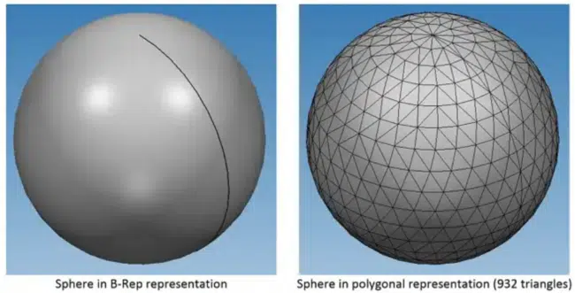
B-Rep Geometry vs. Mesh Geometry (source)
- It represents complex assemblies using part-assembly hierarchies
- It stores metadata
- STEP offers the best support of product manufacturing information (PMI) among the various neutral 3D CAD file formats; in fact, it can represent graphical PMI (polylines meshes, and other displayable entities, semantic PMI (tolerances, surface finishes, dimensions, and more), and associations between PMI annotations and B-Rep geometry
- STEP is supported by a wide range of CAD applications, albeit to varying degrees because while some applications can write PMI to the STEP file, other applications may not be able to read this information, for instance
Weaknesses of the STEP Neutral CAD File Format
- STEP is verbose as it attempts to be as generic and interoperable as possible
- It is associated with larger-than-average file sizes
- It is less accurate because, as a text-based file, it rounds off numerical values, resulting in round-off errors.
2. JT
JT, or Jupiter Tessellation, is a binary file format used as an ISO-standardized exchange format primarily across the entire Siemens Digital Industries Software ecosystem, including NX and Solid Edge. However, it is also supported by a number of non-Siemens software, including SolidWorks, CATIA, Autodesk Inventor, Creo, and more. This means you can import and export parts and assemblies saved using the JT format between multiple software. This underscores JT’s role in promoting interoperability.
From a technical perspective, data in a JT file is grouped based on sections, much like the DWG example above. There is a section that contains metadata, another that contains part-assembly hierarchy, another that stores data on the various types of geometry (including mesh and B-Rep geometry), and, finally, a section that stores visual attributes (i.e., textures, materials, and colors). Simply put, a JT file stores part-assembly hierarchy, visual attributes, geometry data, and metadata.
JT is a lightweight format, firstly because it is a binary format and secondly due to the fact that it uses sophisticated data compression techniques. For instance, JT economically represents mesh data using topological compression algorithms to define the connectedness of mesh patches. These techniques include a lossless compression algorithm and a lossy geometry compression approach that leads to greater compression. Combined, these attributes make JT files smaller than STEP files even when they are used to represent or store comparative models and geometry.
Strengths of JT Neutral CAD File Format
- The JT file format is lightweight and results in small file sizes
- It stores a variety of CAD data, including B-Rep and mesh geometries, metadata, visual attributes, and part-assembly hierarchy
Weaknesses of JT Neutral CAD File Format
- It is complex, an aspect that affects independent implementers of the JT specification
- The quality of JT support varies from one software vendor to another. So varied is this support that JT files, created by Siemens tools descending from the original JT reference implementation – Direct Model toolkit – may not conform to the specification
- Its representation of B-Rep geometry (i.e., mathematical representations of the geometric boundaries between non-solid and solid geometries) falls behind that of the likes of Parasolid
3. X3D
The Extensible 3D file format, often shortened to X3D, replaced the Virtual Reality Modeling Language (VRML). Thus, it is very similar to VRML but boasts a few improvements, many of which have catapulted it to our list of the best neutral 3D CAD file formats. X3D, for instance, has a larger scope than VRML, thanks largely to the fact that its specification has evolved over the years. As a result of this evolution, X3D supports more elements and model attributes than VRML.
X3D is a text-based file format that is made up of nodes. Each node stores certain information regarding the model, including its position within the model as well as the geometry, appearance, and structure of the model. In addition, X3D stores metadata as well as information related to the hierarchical structure of the model. Additionally, and given that VRML was originally intended to describe virtual interactive worlds, X3D stores scene data, including lighting and shaders, keyframe-based animations, particle effects, rigid body physics, and more.
This neutral file format is particularly useful when you need to store mesh models in a manner that preserves both the model hierarchy and all the mesh attributes. It is also preferred when such models have metadata.
Strengths of X3D Neutral CAD File Format
- It maintains the topology of a model by indexing the meshes
- X3D is capable of defining the hierarchical structure of a model
- It can store metadata as well as appearance-related information, including texture and colors
- X3D stores information about lighting, shaders, and rigid body physics
- As a data exchange format, it can designate a model’s elements using CAD terminology or semantics for faces, parts, and assemblies
Weaknesses of X3D Neutral CAD File Format
- VRML and X3D have not been widely adopted, meaning only a few CAD software support them
- Its representation of B-Rep geometry data lags
- Being text-based, X3D files take up more storage space
- It has precision limitations due to round-offs of numerical values
4. IFC
Industry Foundation Classes or IFC is primarily used in Building Information Modeling (BIM) software. In fact, it is designed to facilitate the neutral exchange of BIM-specific data and is supported by many BIM software. TThe IFC neutral CAD file format, which appears to be inspired by several elements of the STEP specifications, recognizes the wide scope of BIM and opts to take a modular approach to storing BIM data. IFC uses Model View Definitions (MVDs), which are use case-specific.
For instance, if an architect or engineer intends to use a design for structural or energy analysis, the IFC’s use of MVDs ensures that the exporting and importing software applications implement only those aspects of the format that are necessary for this workflow and purpose. This way, IFC avoids storing unnecessary information, which may increase the file size.
In addition, IFC stores metadata and entities specific to the construction and architecture space. Examples include building elements such as walls and doors, structural elements such as columns, beams, and slabs, and entities for HVAC systems, piping, and wiring, just to mention a few. The format represents this data in the form of generic geometries that can be read by any software that supports it. Additionally, it uses element-specific attributes that borrow from construction and architecture terminologies.
As a BIM-oriented neutral CAD file format, IFC provides facilities that support processes such as construction, operation, costing, and design. In fact, it features entities that outline the various steps that bring the processes to fruition, the resources required, and the sequence of steps.
Strengths of IFC Neutral CAD File Format
- While this neutral CAD file format is primarily used within the BIM space, it can be used to transfer data from mechanical CAD data, provided the software supports the lossless implementation of the format
- It facilitates the seamless exchange of BIM data
- IFC is suited for individuals in the construction and architecture domains
Weaknesses of IFC Neutral CAD File Format
- Earlier versions of this neutral file format do not support B-Rep geometry, instead representing objects using basic constructive solid geometry (CSG) shapes such as spheres, cuboids, cylinders, cones, and more
- IFC cannot be used to transfer CAD models that are made up of parts and subassemblies because it lacks instancing (duplication) capabilities for these entities
- IFC is generally unsuitable as an exchange format for non-BIM data
5. COLLADA
Short for COLLAborative Design Activity, COLLADA is a file format that uses the .dae file extension. It is a standardized version, specified as ISO/PAS 17506:2022. Though managed by Khronos Group, a non-profit technology consortium, its specifications and schema are freely available, an aspect that has seen it widely adopted by many software tools. From SketchUp, SolidWorks, FreeCAD, and Vectorworks, to 3ds Max, Maya, Blender, Cinema 4D, and Adobe Photoshop, just to mention a few.
COLLADA was designed and released in the early 2000s as a format that would facilitate the transfer of design data from one DCC tool to another. Many years on, this is still its forte – it is primarily used to share 3D models and digital images. Its utility stems from the fact that it can store a lot of details, including color, lighting, texture, background, and other scene data. In addition, this neutral CAD file format stores 3D shapes as mesh geometries.
In addition, its specification enforces metadata usage in exporting and importing software. This attribute makes it particularly ideal for exchanging CAD data. What’s more, it supports physics simulations. This way, it enables designers to transfer data related to the definition of the physical attributes of modeled objects.
From a technical perspective, COLLADA uses an XML-based schema, text-based schema definition language. This means that much like the X3D and STEP, COLLADA is largely text based. Unfortunately, for this reason, the files are larger.
Strengths of COLLADA Neutral CAD File Format
- COLLADA stores metadata
- It also supports scene, appearance, and geometric information
- It is compatible with many software tools
Weaknesses of COLLADA Neutral CAD File Format
- Its use results in large file sizes, considerably larger than OBJ files, for instance
6. OBJ
Created in the 1980s, OBJ was initially intended for use in a 3D animation software package known as Advanced Visualizer, developed by Wavefront Technologies. As such, it aimed to facilitate data transfer between the various software tools that formed part of the package. This built the data exchange foundation on which OBJ stands many years on – it is currently a standard 3D format used for the exchange of CAD data.
Like STEP, OBJ is a text-based format that stores geometries such as faces, vertices, normals (depiction of the orientation of a surface), and texture coordinates. Each of these elements is stored as a line on the text-based file. However, this neutral file format does not store the colors, materials, and textures of objects. Instead, it invokes this information from a separate Material Template Library (MTL) file format. MTL is an ASCII-based companion file for OBJ files, acting as a library that contains named material definitions, as well as specifications of textures, colors, and reflection characteristics.
OBJ stores the objects using meshes that are made up of indexed triangle sets. Its structure is simplistic, making it easy to work with or implement. And despite having been created by Wavefront Technologies, it is an open format. Coupled with the ease of implementation, this has made OBJ a widely adopted neutral CAD file format. Most CAD applications understand the format and can export or import 3D models.
Strengths of OBJ Neutral CAD File Format
- OBJ is supported by many 3D CAD software
- It stores color, texture, and material information, albeit in MTL files
- OBJ is easy to implement and can be extended to store custom data types
Weaknesses of OBJ Neutral CAD File Format
- It does not store metadata
- This neutral CAD file format lacks built-in compression algorithms, meaning the file size can balloon considerably when dealing with large models
- It lacks various features that are standard in other 3D formats, neutral or otherwise, including the level of detail (LOD), lights, animations, and advanced materials
- It does not have the requisite structure to support instancing and nesting, which are integral processes in CNC machining
- Given that OBJ can be implemented in custom ways, support for this neutral CAD file format varies from one software to another, meaning some importing software may ignore data that an exporting application stored in the file
7. STL
STL, an acronym that stands for stereolithography, is a format that boasts simplicity. It is primarily used in the 3D printing space and is widely supported by many, if not all, 3D modeling software. By some accounts, STL also stands for Standard Triangle Language or Standard Tessellation Language. This is largely thanks to the fact that it represents 3D models using 3D meshes. These meshes consist of interconnected triangles, with each triangle’s three vertices containing coordinate-based information. Put together, the coordinate information, as well as the collection of triangles, help define the surface of the model. It is worth pointing out that the more the triangles, the better resolution of the model.
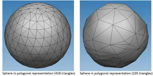
Illustration of the Effect of the Number of Triangles on the Resolution (source)
There are two variants of the STL format, an ASCII and a binary variant – the former results in larger file sizes than the latter.
Strengths of STL Neutral CAD File Format
- It is universally supported by 3D CAD software
- Nearly all 3D printers support it
- STL files are usually smaller in size as they do not contain texture or color information
Weaknesses of STL Neutral CAD File Format
- There is a lack of standardization, with support for STL files varying from one software to another
- It does not store part-assembly hierarchy information
- It does not store color or texture information
- This neutral file format does not specify the units used in the file
- STL file format does not support vertex normals, meaning it is incapable of displaying smooth-appearing surfaces; as a result, models exported using STL appear faceted rather than smooth, as in the image below
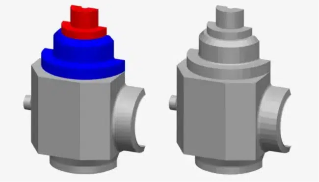
OBJ’s Smooth Curves vs. STL’s Faceted Curves (source)
Conclusion
Neutral CAD file formats offer numerous benefits over both native and geometric modeling kernel formats. Chief among these benefits is high interoperability. Neutral formats can be read and written by numerous CAD applications, while the other formats can only be opened by a few supported programs. It is worth noting that most neutral CAD file formats retain the information defining the model’s scene, geometry, appearance, and metadata when transferring CAD data from one software to another. In fact, our list employs criteria such as level of detail, complexity, compatibility with major software, industry support, and file size to select the various formats discussed. Considering these factors, some formats are superior to others, as summarized below:
- Best overall neutral 3D CAD file format: STEP
- Best neutral CAD file format for the exchange of interactive data (e.g., animations and 3D models): COLLADA
- Best neutral CAD file format for BIM: IFC
- Best neutral CAD file format for 3D printing: STL
