Manufacturers have continually evolved their practices seeking enhanced efficiency, speed, precision, quality, and cost reduction. Computer-aided manufacturing (CAM) has emerged thus, along with other useful technologies. CAM, in particular, is increasingly utilized in automating many manufacturing processes and operations as the culmination of a long process that begins at the design stage and includes structural analysis. It has automated steps that were previously manual, resulting in fewer errors, timely delivery of NC programs (which reduces lead time), and sustained quality. To put it more concisely, CAM has played – and continues to play – a huge role in manufacturing. In this article, we delve into the revolutionary world of computer-aided manufacturing, detailing what CAM is, what CAM systems do, the history of CAM, the future of CAM, and applications of CAM in various industries. Let’s get started.
Table of Contents
Computer-Aided Manufacturing and Its Role in Manufacturing
What is Computer-Aided Manufacturing (CAM)?
Computer-aided manufacturing, abbreviated as CAM, is the use of software to control machine tools, thus automating a particular manufacturing process. It is a type of manufacturing automation process known as programmable automation. CAM is the last in a series of steps that involve modeling a design in computer-aided design (CAD) software. Next, computer-aided engineering (CAE) tools analyze and verify the product design; only then is the product ready for the production stage.
What does CAM Software Do?
The production stage begins when the file containing the product model, i.e., the CAD model, is imported into the CAM software. This file contains vector-based graphical information defining the product’s geometry and its features. However, the CAD file alone is insufficient for manufacturing. Accordingly, the CAM software requires the user to provide additional information such as the machine, available tools, materials, post-processor, the machine’s maximum supported feed rate, supported feed acceleration and deceleration rates, and machine duty cycle.
By combining all this information, the software establishes the desired cutting/tool path, feed rate, and cutting speed. It can also simulate the machining/manufacturing process, depending on the software capabilities. This way, it enables the user to identify errors in such aspects as the generated tool path or cutting approach.
Lastly, using software known as post-processors, it generates CNC programs. These comprise lines of code documenting all these steps, toolpaths, and other manufacturing information, such as the tool’s retraction and height above the workpiece. It is worth pointing out that post processors create the proper G-code needed to operate your specific machine. This G-code conforms to the machine’s conventions, meaning it cannot be universally deployed in all machines. This means that the post processors are not agnostic; rather, they are custom and tuned for use with specific machines. Thus, you must install your machine’s custom post-processor whenever you are setting up your CAM software.
Once generated, the programs are transferred to a machine’s control unit which subsequently dictates its operations and tool movements. Simply put, the machine relies on these programs to create geometric features on a part.
History of CAM
Not familiar with the evolution and history of CAM? Worry not; this section got you covered. CAM evolved from the manual NC programming technique popular in the 1950s. At that time, numerically controlled (NC) machines, which consisted of a controller, several motors moving the cutting tool along a particular path, and a machine tool, already existed. The controller, in particular, was responsible for executing commands contained in NC programs, which were nowhere near as user-friendly, advanced, and intuitive as what we are used to today. However, due to limited storage capabilities, programs were represented as punched holes on a piece of paper, with a specific set of holes signifying a particular command.
This manual approach to programming was nonetheless inefficient. And as engineers sought efficiency, NC machines and manual programming evolved, birthing CNC machines and CAM. The advent of both CNC and CAM started in the 1970s, a time when machines with RAM and storage capabilities became commercially available, and personal computers started to become affordable. However, CAM was still not as advanced as the present generation. This was especially because it was still at the experimentation stage – programs were mostly written by specialists, with most of the calculations taken up by the software. But by 1990, PC-based CAM software was responsible for much of the programming, taking up that responsibility from operators. And by 2000, CAM could automatically create NC programs.
What is the Role of CAM in Manufacturing?
The role of CAM in manufacturing is undeniable, as it controls numerous modern machines designed to perform a wide array of functions, including wood and metal cutting operations. These functions include:
- 3D printing: Also known as additive manufacturing, 3D printing creates 3D objects or parts by extruding material layer by layer according to the parameters in a CAD file.
- Plasma cutting: This method uses a high-energy state, electrified gas to cut material; the plasma cutter injects an electric current into a compressed airstream that is then channeled through a nozzle
- Drilling: This process is used to produce holes.
- Reaming: It is used to enlarge holes or improve the surface finish, roundness, or size accuracy of the holes.
- Milling: This metal-cutting process uses a rotating cutter to remove material from the surface of a workpiece
- Sawing: This operation uses a serrated blade or grinding blade to cut long bars of wood or metal into thin bars
- Laser cutting: This method uses highly focused heat to cut through material
- Spinning: In the textile industry, spinning refers to the process of turning raw materials into yarn. In contrast, metal spinning refers to a process where a tube or disc rotating at high speed is reshaped using a roller tool.
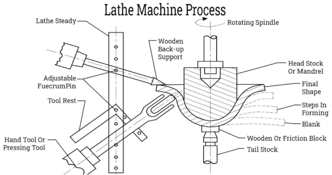
Metal Spinning Process using a Lathe Machine (source)
- Bending: This operation deforms a material to a certain shape along a particular straight axis
- Waterjet cutting: This method utilizes a highly focused, high-pressure stream of water to cut a range of materials, including foam, glass, and metals
- Grinding: This is an abrasive machining process that removes material from the surface of a workpiece to achieve a particular finish
- Planing: This process is used to produce flat surfaces
- Shaping: This machining process produces various contoured surfaces
- Tapping and threading: Tapping produced threads along the internal surface of a hole, while threading produces external threads
- Turning: This metal-cutting process is carried out using lathes; in turning, the cutting tool is fed into the external surface of a rotating workpiece, which is parallel to the axis of rotation.
- Boring: This process is performed using lathes, drilling machines, or milling machines; it usually involves working on the internal surface of a workpiece and is mainly utilized for roughing, finishing, or semi-finishing drilled or cast holes.
- Parting: This process is used to cut the finished product away from the raw material
By providing automation, computer-aided manufacturing offers a number of benefits. Generally, CAM helps reduce lead times in production. Lead times refer to the period between when a customer or an employee orders a product and when the product is delivered. Moreover, CAM improves productivity by taking up the programming role and freeing operators and machinists to work on other important tasks.
But that’s not all; this integral automation approach also promotes sustained quality, as it can simulate the manufacturing process. This enables engineers to make changes that optimize the steps or correct errors, and it also allows operators to edit the generated NC program. CAM software is also incredibly versatile and flexible. These systems can be used not only to create programs from simple CAD designs but also to work with complex 3D models. Other notable benefits include reduced manufacturing/production costs and the simplification of complex calculations.
What is the Relationship between CAM, CAD, CAE, and CNC?
Computer-Aided Design (CAD), Computer-Aided Engineering (CAE), and Computer-Aided Manufacturing (CAM), collectively known as Computer-Aided Techniques (CATs), along with Computer Numerical Control (CNC), are interconnected and interdependent. While CATs can operate independently – and indeed, there are numerous CAD, CAE, and CAM tools available in the market – they serve to complement and enhance each other.
As introduced above, CAD enables designers to create 2D drawings and 3D models that are defined by geometrical objects and dimensions. In addition, CAD systems feature a graphical user interface that lets designers view objects and visualize their creations. But in isolation, CAD software cannot be used to conduct analyses such as finite element analysis (FEA), computational fluid dynamics (CFD) that facilitates thermal and fluid analysis, and kinematic and dynamic analysis, just to mention a few. Thus, CAE systems, which are specifically designed to analyze models, enter the picture.
But CAE can only be used for analysis, yet the models are supposed to be manufactured using automated approaches. At this juncture, i.e., once all the necessary analyses have been conducted, CAM then picks up where CAE leaves off by converting the now-analyzed design data to code that controls CNC machines. In this regard, the latter components in the CAD-CAE-CAM-CNC pipeline are more or less dependent on the tasks performed by the former. Within the manufacturing context, there is no CNC without CAM, CAE, or CAD. Similarly, there is no CAD without CAE, CAM, and CNC.
CAD/CAM Systems
No one understands this relationship better than the developers of CAD, CAE, and CAM systems. This understanding has led them to create CAD/CAM software that amalgamates the capabilities of these individual systems, providing a powerful, convenient all-in-one solution.
Ordinarily, when dealing with separate systems, you would need to constantly export and import files. For instance, upon creating a model in CAD and preparing the CAD file for CNC machining, you would traditionally have to export that file and then import it into CAE software. Here, you would analyze the model and subsequently export the file and export it to CAM software. Then, the CAM system would enable you to convert the design data to a CNC program using a built-in post-processor. At this point, you would export the program, transferring it to the CNC machine. These steps, while necessary, are monotonous and could be streamlined. This is the reasoning behind the development of CAD/CAM systems – the aim is simplicity.
CAD/CAM systems are quite common. In fact, the most popular 3D modeling software – Fusion 360, SolidWorks, Creo, FreeCAD, Solid Edge, and NX – have CAD/CAM capabilities. (All you have to do to harness the CAD/CAM capabilities, thus converting some of this software from CAD to CAD/CAM, is to install a CAM add-in/extension into the CAD package.)
Computer Aided Manufacturing (CAM) Software
There are multiple CAM solutions designed as either standalone products or add-ins/extensions that can be integrated into CAD software. In this article, we will discuss a few select computer-aided manufacturing products and/or extensions, which include:
CAMWorks
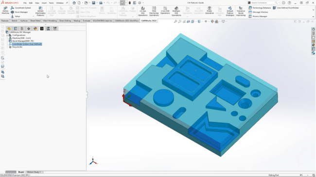
CAMWorks in SolidWorks (source)
CAMWorks is an add-in that can be integrated into a variety of CAD applications, such as SolidWorks and Solid Edge, effectively transforming them into CAD/CAM systems. This way, users no longer need to maintain separate CAD and CAM files. Moreover, they do not have to constantly export and import these files from one system to another. Plus, this arrangement eliminates data translation issues.
Features of CAMWorks
- It automatically updates the toolpaths and G-code whenever designers make changes to the model/design
- Feature-based programming
- Automatic feature recognition, which means the software automatically interprets the design
- Knowledge-based machining
- It can save user preferences for reuse on future projects
- Support for milling (up to 5-axis milling), turning, mill/turn multitasking, wire electrode discharge machining (EDM), routers, lasers, waterjets, probing, and more
Solid Edge CAM Pro
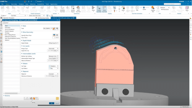
Solid Edge CAM Pro
Solid Edge CAM is a modular (or standalone) computer-aided manufacturing software that offers a wide range of NC programming capabilities. In addition to being CAD-neutral – it can accept files from a myriad of CAD software – it has an intuitive and modern user interface, with wizard guides and online tutorials that make it easy to use. Moreover, it expands the capabilities of Solid Edge Classic by supporting 2.5-axis, 3-axis, and 5-axis milling capabilities, whereas the Solid Edge Classic only supports 2.5-axis milling. Other notable features and capabilities include turning, simulation, feature-based machining, and milling.
Features of Solid Edge CAM Pro
- Post Hub – an online library of more than 1,200 post processors
- It has the flexibility to be used independently of any specific CAD system
NX CAM
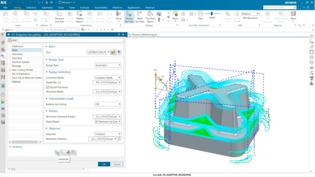
NX CAM (source)
NX CAM is a dedicated computer-aided manufacturing solution that automates NC programming, consequently reducing machining time. Its CAM capabilities comprehensively cover simulation, programming, machining, and advanced toolpath technologies. As a result, it can generate NC programs for even the most complex and high-precision parts.
Features of NX CAM
- G-code-driven integrated machining simulation that displays the motion hardcoded in the NC code
- Cloud-based post-processing kit with over 1,000 post processors
- Complex parts machining thanks to precisely controlled 5-axis toolpaths
- Mold, die, and electrode machining, which supports multi-axis machining, smooth finishing toolpaths, automated rest milling, and high-speed cutting methods
- Volume-based milling and 2.5-axis milling
OpenBuilds CAM
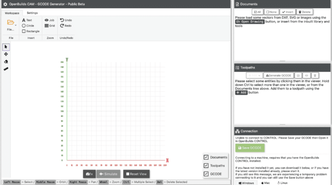
OpenBuild CAM Web Application User Interface (source)
OpenBuilds CAM is a free web-based CAM application that converts DXF, SVG, PNG, JPG, and Bitmap drawings to G-code. It is designed to generate toolpaths for CNC routing, plasma, and laser cutting. Once the CAM solution is generated, the G-code is relayed to OpenBuilds CONTROL, an application used to connect and control CNC machines.
Features of OpenBuilds CAM
- It is a web-based system
- It is suited for laser cutting, plasma cutting, and CNC routing
CAM Tools
A good computer-aided manufacturing software system should be able to program the various manufacturing processes supported by a variety of CNC machines. These processes require different types of tools. For instance, casting or injection molding processes need molds; material removal processes such as those listed above require cutting tools, e.g., lathes, mills, and plasma cutters; and metal forming processes need dies.
An important task you need to accomplish while preparing your CAD design for CNC machining is specifying the tools you intend to use, among other things. But if you are just starting out in this field, you may not completely grasp the types of tools available. This is why this section is dedicated to providing this knowledge.
Types of Supported CAM Tools
The different CAM tools you are likely to encounter include:
- Mold: a mold is used to shape a product in a forming process such as injection molding or casting
- Die: a die is used to shape a product in a deforming process such as stamping and forging.
- Turning tools: These tools move along a single axis, removing material from a rotating workpiece
- Milling tools: These tools, which feature multiple cutting edges, rotate relative to a stationary workpiece, thus removing material when contact is made
- Drills: These tools create holes, meaning they are end-cutting tools. Drills have straight or helical/spiral flutes and can have a hollow body to facilitate cooling fluid passage.
- Boring bars: These tools work on a workpiece’s internal surface and are mainly used for roughing, finishing, or semi-finishing drilled or cast holes.
- Form tools: These are used to cut a defined profile on a rotating workpiece in a single plunge cut; they are categorized under turning tools
- Deburring tools: These are chamfering tools that remove undesired projections of materials along the edge of a workpiece, which result from heat-induced plastic deformation
- Reamers: These are rotary tools used to enlarge holes or improve the quality and roundness of the hole.
- Threading tools: These turning tools create threads on a workpiece’s internal or external surface. Examples of threading tools include taps, thread mills, thread-turning inserts, dies, and thread chasers.
- Grinding wheels: These tools are composed of abrasives that remove material from the surface of a workpiece, improving the surface finish
- Honing tools: These are used to create the desired finish pattern on the interior of cylindrical holes. These tools also provide final sizing.
- Parting tools: These are thin blades that produce narrow grooves and are used to cut finished products away from raw materials
For a more comprehensive discussion on various metal cutting processes and cutting tools, please refer to the second and fourth chapters of this book. And as you will notice while scouring through the chapter, there are different subtypes of tools under each category. For instance, form, grooving, cut-off, and threading tools are examples of turning tools. Additionally, you will observe that multiple different tools can be used in the same CNC machine, depending on the intended outcome. For instance, a lathe machine can utilize tools such as deburring, boring, forming, and turning tools.
Applications of CAM in Various Industries
Computer-aided manufacturing technologies have impacted the way professionals in numerous industries work. Broadly speaking, it has improved the speed, precision, quality, and accuracy of their work. But to understand this impact in greater detail, let’s take a nuanced approach that looks at how CAM is applied in each industry.
CAM in Heavy Industry Manufacturing and Industrial Equipment Production
Heavy industries produce large and heavy products such as large machine tools and heavy equipment, e.g., ships, wind turbines, excavators, rockets, trains, aircraft, marine engines and machinery, and more. Such industries normally utilize a number of manufacturing and machining processes. And despite the sheer number of steps, materials, and tools involved, the plants still need to maintain precision, quality, and efficiency while maximizing production capacity.
Therefore, CAM software proves to be an essential tool. Such systems have been optimized to create efficient toolpaths based on streamlined drilling, trimming, or cutting processes. For its part, MasterCAM, for example, offers a bunch of built-in proprietary tools that are particularly beneficial in heavy industry machining. For instance, its Accelerated Finishing™ tool enables manufacturers to achieve better surface finishes using fewer passes. Additionally, the Dynamic Motion™ technology, which continually adjusts the cutting motion of the tool to maintain constant chip thickness, extends tool life and decreases cutting time.
CAM in Medical and Life Sciences Manufacturing
Medical and life sciences manufacturing covers such sectors as biomedical devices, life systems technologies, nutraceuticals, biotechnology, and pharmaceuticals. Here manufacturers use a wide variety of machinery to develop medicines, technology, and medical equipment.
The creation of medical equipment is a multi-stage process , encompassing conceptualization, planning, design (where CAD comes in), CAM prototyping (which involves the use of CAM to convert CAD designs into machine-controlling code, often producing prototypes with minimal waste), testing, design verification, validation, and ultimately, medical device manufacturing.
CAM in Tool Creation Industry
For its part, CAM software handles calculations as well as programming, meaning it reduces the chances of errors. This proves beneficial in creating tools, molds, and dies, as these processes focus intensely on accuracy, precision, and strict tolerances. While manual programming might be an alternative approach, it can be plagued by human error, which affects accuracy and precision.
CAM offers mold and die solutions for creating progressive dies and mold bases, their cores, and cavities. Moreover, the software generates efficient toolpaths for creating each of these tools, resulting in a seamless workflow.
CAM in Woodworking
Customers have come to expect two main things from woodworking shops – utility and beauty. But meeting these expectations can sometimes prove challenging, especially if the customers require complex components, e.g., intricate handrails. Fortunately, CNC woodworking is gaining prominence thanks to its assurance of precision and efficiency while guaranteeing profitability. In fact, CNC also offers repeatability. But the benefits of CNC machines in woodworking can only be realized using CAM software.
Computer-aided manufacturing software controls routers and sawing machines, both central to woodworking. For example, CNC routers controlled by CAM can be used to etch images and text to create signs. CNC lathes can also be used in woodworking to create beautiful, complex handrails. Similarly, a CNC mill can be used for wood products that require material to be shaved off from an internal surface. But for production shops to achieve the accuracy and precision required for each of these products, CAM software, which hardcodes the steps and toolpaths into NC programs, is absolutely essential.
CAM in Textile Industry
CAM systems can automate the entire textile manufacturing process, from yarn manufacturing (spinning), fabric manufacturing, and wet fabric processing (i.e., dyeing) to fabric cutting and measurement and garment manufacturing.
CAM in Transportation and Automotive Manufacturing
The transportation industry is punctuated by mass production. Even so, precision and reliability are paramount. Failure to create reliable products and precise fits has often led to recalls, which can eat into automotive companies’ profits. Furthermore, imprecise fittings or technologies can be disastrous in mass transit vessels. For this reason, designers, machinists, and all professionals in the supply chain should always emphasize accuracy, reliability, precision, and quality. One way they can achieve this is to blend CAD and CAE with CAM systems, which automate the manufacturing process.
Advanced CAM software provides capabilities that are suited for the automotive and transportation manufacturing sector. For instance, some software includes strategies that improve the production of molds. Others create programs that automatically adjust the feed rates and cutting speeds to reduce tool wear. This is particularly important in mass production.
CAM in Education
Manufacturing necessitates the transfer of skills from experienced professionals and educators to novices. In this regard, educators use CAM to introduce students to this trade and give them hands-on experience and skills on how to use the software.
CAM in Aerospace Manufacturing
Aerospace manufacturing is an extensive industry that can be segmented into commercial and defense aerospace manufacturing. It involves the manufacture of space vehicles, aircraft, missiles, engines, and parts, in addition to services such as maintenance, repair, and overhaul. In this context, precision, reliability, and speed are critical to success, considering the limited number of players in the market (with Boeing and Airbus leading), and any mistakes can have catastrophic consequences.
Thus, CAM solutions are employed to meet the rigors of the industry. Such tools not only generate efficient toolpaths that optimize machining and reduce lead times but can also handle complex machining challenges. In fact, computer-aided manufacturing software does support the various manufacturing processes deployed in aerospace manufacturing.
CAM in Consumer Goods Manufacturing
Consumer goods are products made for consumption by the average consumer. They include clothing, food, drinks, toothpaste, household appliances, bicycles, and so on. Such products are manufactured using batch production, given the manufacturers’ need to maintain high quality control, among other factors.
Manufacturing consumer goods is a specialized trade. In most cases, a plant is designed only to manufacture a particular type of good. In such plants, the manufacturing processes are not changed frequently, meaning that programmable equipment is preferred. And given that CAM software is used to write NC programs that drive the equipment, CAM is prevalent in consumer goods manufacturing. Additionally, this software can accept virtually any CAD model and subsequently create programs for even the most complex molds used to manufacture consumer products.
Another argument that supports CAM in consumer goods manufacturing lies in the fact that programmable automation is particularly useful in batch production where the volume of output is medium to high. This, therefore, makes the case for this kind of manufacturing which is characterized by high volumes.
CAM in Oil and Gas Production
Oil and gas production takes place on land or in the deep sea, in environments as harsh as they are inhospitable. The varying characteristics of production fields mean there is no one-size-fits-all approach to designing and manufacturing products, particularly those used in offshore oil and gas platforms. Additionally, there are always environmental considerations, meaning the connections, pipes, and other components should be strong, fit perfectly, and be tightly sealed to avoid spillage or bursts at high pressure. All these factors point to precision design and manufacturing, and that is where CAM comes in. Moreover, CAM software can be used to automate the manufacture of drills.
CAM in Additive Manufacturing
Additive manufacturing or 3D printing is a rapid prototyping technology developed in the 1980s. It fabricates physical 3D objects of complex virtual structures created using 3D CAD software. CAM software is perfectly suited for 3D printing. It enables you to optimize, validate, and run print checks even before you can start the printing task. This way, the system helps you identify and resolve mistakes and reduces the printing time once the task begins. Additionally, CAM software can create and optimize 2.5D and 3D lattice structures and facilitate the seamless analysis and optimization of the lattice. Additionally, it can be used to set up the printer tray, optimize nesting, and generate and customize support structures.
Advantages and Limitations of CAM
Advantages of CAM
- It reduces lead time in manufacturing. This is because the programmer does not have to manually type the NC code. The code is generated automatically, reducing the time to market.
- It sustains the consistent quality of a product by helping users avoid programming errors, which are common with manual programming. Additionally, CAM software such as MasterCAM lets users edit G-code
- CAM enables engineers to detect design defects and subsequently modify the designs, especially because it can simulate the manufacturing process
- It offers greater flexibility in manufacturing, as it can create programs for both simple and complex forms
- CAM systems have built-in RPM calculation that helps them automatically determine the correct cutting or drilling speed
- Computer-aided manufacturing simplifies the operation and programming of CNC machines
- Most CAM software can automatically update the generated program if there’s a change in the geometry of the model
- CAM reduces manufacturing costs by reducing errors that may cause wastage and lead times
- It facilitates the evaluation of the performance of production systems in a virtual environment
- It provides engineers with a visual tool to model and analyze manufacturing processes, including simulation capabilities
- CAM increases the productivity of operators and machinists. These professionals no longer have to manually program every step, which can take up valuable time
- Computer-aided manufacturing software can program even the most complex parts, something that cannot be achieved via the manual approach
Limitations of CAM
- Applying CAM techniques requires skilled personnel as some CAM systems have steep learning curves
- It requires a high initial investment to purchase CNC machines as well as procure CAM systems
Future of CAM
Previous Predictions in CAM
A while back, in 2018, Autodesk wrote about what the future of CAM would look like. The article highlighted advancements such as the standardization of CAM with XML technology. XML was expected to increase the portability of designs across software platforms. Cloud computing, quantum computing, and emerging input/output methods were also featured in the article.
Since the prediction, multiple developers have gotten involved with VR/AR as an alternative output method. Additionally, software such as Solid Edge, Fusion 360, and SolidWorks save or load data files stored in XML. However, the progress in quantum computing is nothing to write home about as this technology is still at a nascent stage. But what lies ahead?
What Lies in the Future of Computer-Aided Manufacturing
Integration of CAD and CAM Systems
While we cannot accurately predict the future, we can uncover trends that point to the direction computer-aided manufacturing is headed. Firstly, dedicated CAM software is likely to be replaced by CAD/CAM software. (As detailed earlier, CAD/CAM systems combine the capabilities of CAD, CAE, and CAM into a single interface.) With this integration, we might start to see a merging of the different roles.
AI in Computer-Aided Manufacturing
Secondly, the artificial intelligence (AI) bug is unlikely to miss the CAM space. As discussed extensively in an earlier article, AI is playing a vital role in the CAD industry. But what about manufacturing? Already, manufacturers such as BMW are implementing AI-backed solutions to optimize production. For instance, BMW partnered with Nvidia to create a virtual (digital twin) factory. Within this virtual factory, machine-learning algorithms simulate robots performing complex tasks to identify the most efficient processes. In addition, the virtual factory is also intended to train workers. Against this backdrop and within the context of CAM, we foresee a scenario where AI and machine learning (ML) algorithms are integrated into the software to find the most optimal machining methods and toolpaths.
As it stands currently, the available CAM software applications are not perfect. Of course, they are capable of generating efficient toolpaths. But you are likely to encounter situations where the selected path is not quite optimal based on your shop’s machining practices, as this user documents. Thus, we expect AI and ML algorithms and models to help improve this issue by training themselves on your preferences and the data generated.
Improved Features and Capabilities
We are also likely to see the introduction of new, improved features and capabilities. This prediction is based on the premise that developers within the CAD and CAM spaces often strive to introduce new features to justify the rollout of new software versions. Moreover, cloud computing is poised to take preeminence, given that easy-to-use cloud-based CAM solutions are likely to become even more popular.
Experts also predict that manufacturing plants will be closely interlinked and share information on resources and processes in real time. Per their assessments, sensor technology, augmented reality, and big data analysis are expected to usher in a new era of computer-aided manufacturing.
Conclusion
Computer-aided manufacturing (CAM) has revolutionized multiple industries thanks to its contribution to automation. By converting design data to G-code, CAM software helps automate manufacturing processes, which promotes accuracy, precision, speed, and quality. These benefits have made CAM a vital addition to various industries, including life science and medicine, heavy industries, aerospace and defense, textile manufacturing, oil and gas production, additive manufacturing, and more. While computer-aided manufacturing offers numerous advantages, it does have some limitations. These include the initial investment cost and the skill set required of designers and operators. Nonetheless, this might be a small price to bear in the larger scheme of things, especially given that CAM is here to stay. Looking ahead, CAM is expected to be much more improved. This is thanks to the infusion of emerging technologies such as artificial intelligence, digital twins, and big data analysis.
