3D printing and Computer Numerical Control (CNC) machining are some of the most popular processes. While the former is an additive method in that it involves adding molten material in layers to form a physical 3D model, the latter is subtractive. CNC machining entails using milling tools to remove material from a block in order to create a 3D model. At the center of 3D printing are two common and universal file formats: STL and Virtual Reality Modeling Language (VRML). On the other hand, CNC machining and the movement of parts within a 3D printer are driven by a programming language known as G-code.
While STL is a popular 3D printing format, its utility does not go beyond simply representing the outer surface of a 3D model. Simply put, it stores information that describes a 3D object, nothing more. Thus, when it comes to 3D printing, the STL model must first be converted to G-code. It is the instructions contained in the G-code that will dictate the movement of the 3D printer to create the 3D model initially portrayed by the STL file. In this regard, every 3D printing job requires you to use software known as slicers that convert STL to G-code. And this article explores how you can achieve the STL to G-code conversion.
Table of Contents
What is STL Format?
STL is an acronym for STereoLithography (an industrial process of printing 3D models or objects), Standard Triangle Language, or Standard Tessellation Language. The file format was created in 1987 by 3D Systems, a Rock Hill, South Carolina-based engineering company that designs, manufactures, and sells 3D printers, 3D scanners, and 3D printing materials. Since its creation, the format has grown in popularity and utility and is now synonymous with 3D printing.
The popularity of the STL format stems from the need to standardize 3D modeling and printing. This is because you can digitally create 3D models using various CAD programs, each of which has a native file format. If a 3D printer were to support and process each of these formats, it would need plenty of computing power. So, the STL format, which can be exported by most of these CAD programs, is preferred to aid in minimalism.
The format digitally represents 3D models using a 3D mesh that consists of triangles. The interconnected triangles (triangle tessellation) describe the surface of the 3D model or object. Each of the vertices of these triangles contains coordinate-based information. Once combined, the vertices approximate the limits of the model and hence, the surface. The number of triangles used depends on the complexity and resolution of the model. For example, a complex design has more triangles and, therefore, has a higher resolution. On the other hand, a simple model will have fewer triangles.
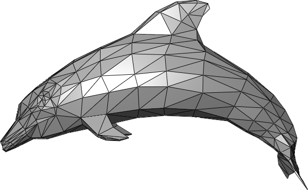
Dolphin triangle mesh (source)
Uses of the STL Format
The STL format is used for the following use cases:
- 3D printing
- Rapid prototyping
Advantages and Disadvantages of STL Format
Pros of STL Format
The advantages of the STL file format are:
- Universality
The STL format is supported by most CAD programs and packages, as well as image editing software such as Photoshop. In addition, the format is supported by nearly 100% of 3D printers currently in production. - Versatility
You can utilize the STL format to store various 3D objects, meaning that the format can create a 3D mesh of any object. - Small file size
STL files take up less disk space because it does not store color and texture-based data, nor does it contain metadata. This makes STL files easy to process.
Cons of STL Format
The disadvantages of the STL format include the following:
- STL format does not represent texture or color
It is noteworthy that triangle tessellation only defines the outer surface of the model; it does not define any other characteristic. In that regard, the 3D models that bear the .stl file extension do not have texture or color. - The convexity or concavity of a model cannot be determined with STL
A study done in 2006 has shown that the use of triangles makes it impossible to determine the convexity or concavity of a model, properties that are key when it comes to machining. At the same time, tessellation is often associated with errors in the data structure, which leads to holes and gaps, resulting in open loops in the cross-section. - The format does not store metadata
STL files do not contain essential data such as location or authorship.
Such disadvantages point to the importance of converting STL to G-code
What is G-code?
CAM (Computer Aided Manufacturing) software packages are an essential part of the CNC machining process as well as other manufacturing processes that involve movements along the X, Y, and Z axes. In such instances, the CAM programs generate G-code, which, in turn, defines and controls the movement of machining tools and machines. So, what is G-code?
G-code is a collection of CNC commands or code that are akin to programming languages. It is generated by CAM or CAD software or written by a programmer, packaged as a program or file that is stored using one of several G-code file extensions (.nc, .gcode, .tap, .cnc, or .mpt), and then fed into a machine controller. The G-code program contains instructions that, once executed, dictate how a CNC machine should maneuver in order to create a predefined model by curving it out of a block or piece of a given material. Depending on the router bit as well as other factors, the CNC machine can work on plastic, wood, ceramic, metal, or composite.
In addition to CNC, G-code is also applied in 3D printing. How so? A 3D printer consists of motors that define or control the nozzle movement along the X, Y, and Z axes. These movements result from instructions fed into the 3D printer’s controller via a program written in G-code. The instructions also control other aspects, such as the temperature of the extruded material as well as the cooling process.
Uses of G-code
The uses of G-code include:
- G-code controls CNC milling machines
- G-code contains instructions that dictate the movement of parts within a 3D printer
Why Convert from STL to G-code?
Indeed, STL format is synonymous with 3D printing in that it is used to digitally represent 3D models using 3D meshes. However, the files stored using this format cannot be printed wholly – the 3D models cannot be printed as represented by the meshes. Instead, they must first be sliced to create layers, with each layer defined by G-code.
Why do you have to convert STL to G-Code when printing 3D models? What are the pros of 3D printing from G-code compared to STL? Well, there are a number of reasons and advantages of undertaking an STL to G-code conversion, including:
- STL cannot clearly define the convexity or concavity of a surface
G-code is, therefore, more accurate than STL - The STL format only describes the outer surface of a model
This means that the triangle tessellation does not define the layers that make up the model or lead to the protrusions on the model’s surface. This greatly departs from the fact that 3D printing prints models/objects in layers and would, therefore, better work with a format that defines layers, which is where G-code comes in. - G-code defines the movement of a 3D printing nozzle
It is this movement that, in turn, results in the creation of a physical 3D model. On the other hand, STL only defines the outer surface of the model as it would appear after printing. It does not contain instructions on how the 3D model will be printed. - G-code is easy to edit as it entails changing a few lines of code, while STL files can prove to be quite challenging to edit
How to Convert STL to G-code?
An STL file is converted to G-code through a process known as slicing. Undertaken by a software application known as a slicer, slicing simply converts digital 3D models into printing instructions.
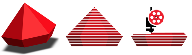
3D Slicing illustration (source)
To convert STL to G-code using a slicer, simply follow the procedure below:
- Upload your STL file (3D model) into the slicer software
- On the software’s interface, tweak the printing parameters by changing settings such as:
- Layer height: the thinner the layers, the better the quality of the finish
- Wall thickness (in the case of hollow models)
- Infill patterns and density
- Retraction
- Temperature and cooling: the temperature you set depends on the material used; when plastics are used, there is a range of temperatures you should use for the printer to produce good-quality prints
- Print speed: a slow print speed generates a good quality print
- Print time: time is a function of the speed and layer height; better quality prints take longer to complete
- Support structures (materials and settings): a good slicer software enables you to choose whether you want to add support; in addition, it lets you make changes such as the support type, support pattern, adhesion type, overhang angle, and more (more on support structures below)
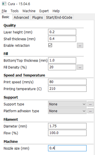
Print Settings on Cura (source)
- Conversion
Once you have made the changes, the slicer converts the printing settings into instructions that are then fed into the G-code file. In following the guidelines contained in the file, the 3D printer produces a physical 3D object/model.
Considerations when Converting STL to G-code
A successful STL to G-code conversion depends on several considerations, including:
- 3D printing technology and 3D slicer’s specialization
It is worth pointing out that there are numerous 3D printing technologies, namely Fused Deposition Modeling(FDM), Stereolithography (SLA), Selective Laser Sintering (SLS), Selective Laser Melting (SLM), Electron Beam Melting (EBM), and more. Each of these technologies requires its own specialized slicer. For instance, Ultimaker Cura (open-source) and Simplify3D (premium) are 3D slicers for FDM, while FormWare and ChiTuBox are 3D slicers for SLA.
- Print settings used
The parameters differ from one slicer to another. For instance, FDM settings include nozzle temperature or cooling, while SLA settings feature parameters such as lifting speed and exposure speeds
- Pricing
Some 3D slicers are available at a fee, while others, like Ultimaker Cura, are freeware
How to Improve your Results when Slicing?
If you’re able to, the best outcome could be achieved by improving the file’s resolution before printing so the model becomes more detailed and accurate.
A slicer will also enable you to set the print settings, which, in turn, determine the quality of the printed model. So, to ensure quality work and improve your results when slicing, you should consider using a slicer software program that contains each of these printing settings. It is also important to consider each parameter’s effect on the quality and subsequently change the settings accordingly.
For instance, you should maintain a given temperature when working with plastic, set a slow print speed, and reduce the layer height for the best results. It is also essential to enable support structures, especially when working with FDM 3D printers. But if you are familiar with such printers, you may have observed that support structures are not always required. So, how do you decide if a 3D model needs support?
Support Structures in 3D Printing
Support structures refer to extra material printed to buttress sections of the 3D model that would otherwise break away before the completion of 3D printing. Simply put, they ensure a successful print. And while they require additional time, material and, as a result, could substantially balloon the cost of 3D printing, support structures are necessary.
These structures are utilized in cases where your 3D model has:
- An overhang (or)
- A bridge
However, not all overhangs and bridges require support structures. Generally, you should enable support if the angle of a plane along the outer edge of the overhang is greater than 45º from the vertical. However, additional factors such as the quality of the 3D printer and the material used also come into play – a lousy printer may fail to print a section that overhangs at an angle less than 45º.
The second parameter relates to instances where a bridge requires a support structure. Typically, if an unsupported vertical structure covers a length of less than 5mm, the 3D printer can print it successfully. However, anything longer than 5 mm would require you to enable the support structure in the settings.
Conclusion
The STL format is used to digitally represent/store 3D models or objects. STL files utilize triangle tessellation to represent the surface of the models. But this comes at a disadvantage when it comes to 3D printing. Typically, 3D printing involves the movement of a printer’s nozzle to create a 3D object. So, printing a model requires the conversion of its digital layout to instructions that can then guide the printer’s movement. In isolation, the STL format does not contain these instructions, which is why it is crucial to convert STL to G-code. On its part, G-code is a set of code-based instructions that dictate the movement of a CNC router or 3D printer.
The STL to G-code conversion is also known as slicing and is undertaken by software known as 3D slicers. For the best possible 3D printing results, it is crucial to choose the appropriate settings. For instance, you have to set the right temperature, speed, layer height, and wall thickness, among other parameters.
