AutoCAD is a commercially-available program for CAD and design work. It was first developed and released by a back in December 1982 and has, since then, slowly put itself above its competitors in the CAD industry. The program has users in the architectural, project management, engineering, urban planning, and graphic design fields.
While most CAD users will be familiar with AutoCAD as a program, not all are familiar with AutoCAD’s Raster Design toolset. The Raster Design toolset allows users to seamlessly use images – be it scanned photos, drone snapshots, digital elevation models, or even satellite images – within the AutoCAD program. The latest version of Raster Design can open all common image formats and can support all the formats that AutoCAD can handle.

Now, most AutoCAD users understand the basics of importing images into their file. Imported images usually contain manual sketches and scanned copies of plans and details that need to be digitized and added to a CAD file. Designers are familiar with the process of scanning initial sketches of a plan or a design detail and creating more refined, digital copies of them by tracing over the initial sketches and fine-tuning the angles and lines. The result of this importing and tracing process is accurate CAD files that can be plotted out as blueprints or fed into CNC or laser-cutting machines for accurate cutouts.
An Image converted to vector by Raster Design (source)
Importing and converting images through AutoCAD is a tedious process. If you’ve ever tried to do it manually before, you’ll know that complex images will sometimes take hours to fully and accurately plot onto a CAD file. There is conversion software online for these types of processes but not all produce accurate and workable output. That’s why Autodesk saw it fit to release Raster Design which is specifically designed to take out most of the tedium in importing image files. In this blog post, we’ll be talking about how to go about using Autodesk Raster Design to its fullest potential.
Table of Contents
Which image types can I import?
To discuss how Raster Design can be used for image importing, let’s first discuss the difference between raster images (the type of images that the program handles) with vector images.
Vector images are made up of formulas and mathematical data that are then processed and translated into viewable images. A vector image of a square is actually a bunch of information that dictates the measurements, outline width and color, and angle of the lines that create the square. CAD files are actually examples of vector images and are what Raster Designs seeks to convert imported images into.
Raster images or bitmap images, on the other hand, are made out of pixels with a designated color assigned for each of these pixels. Put together, they form a coherent and comprehensible image. The different types of raster images that Autodesk Raster Design handles are the following:
- Bitmap (BMP / .bmp)
- Computer-Aided Acquisition and Logistics Support (CALS / .cal)
- Digital Elevation Model (DEM / .dem)
- Digital Orthophoto Quadrangle (DOQ / .doq)
- Digital Terrain Elevation Data (DTED / .dto)
- Enhanced Compressed Wavelet (ECW / .ecw)
- ESRI interchange format (ESRI ASCII Grid / .asc)
- ESRI internal format (ESRI Binary Grid / .adf)
- Animator FLIC (FLIC / .flc)
- SPOT Image Corporation’s raster format with georeferencing format (GeoSPOT / .bil)
- Geo-referenced TIFF (GeoTIFF / .tif)
- Compuserve Graphics Interchange Format (GIF / .gif)
- Image Systems Group 4 (IG4 / .ig4)
- Joint Photographics Expert Group, best suited for 24-bit images (JFIF- JPEG / .jpg)
- JPEG 2000 (JPG2000 / .jp2)
- Multispectral format used by Landsat 7, primarily for multiframe image sets (Landsat FAST-L7A / .fst)
- Multiresolution Seamless Image Database (MrSID / .sid)
- National Imaging Transmission Format; can be multiframe multispectral (NITF / .ntf)
- A simple run-length encoded format (PCX / .pcx)
- Apple Computer format (PICT / .pct)
- Portable Network Graphics (PNG, .png)
- Adobe Photoshop (PSD, .psd)
- Images from DigitalGlobe’s QuickBird satellite; typically multiframe, multispectral, but can also be single-frame panchromatic (QuickBird TIFF, .tif)
- Run-Length Coding with no header (RLC1, .rlc)
- RLC with IST headers (RLC2, .rlc)
- Format developed by Truevision Inc. Usually 24-bit true color; can be 8-bit grayscale or simple run length encoded (TARGA, .tga)
- Tagged Image File Format, developed by Aldus Corporation (TIFF, .tif)
How to insert an image into Raster Design
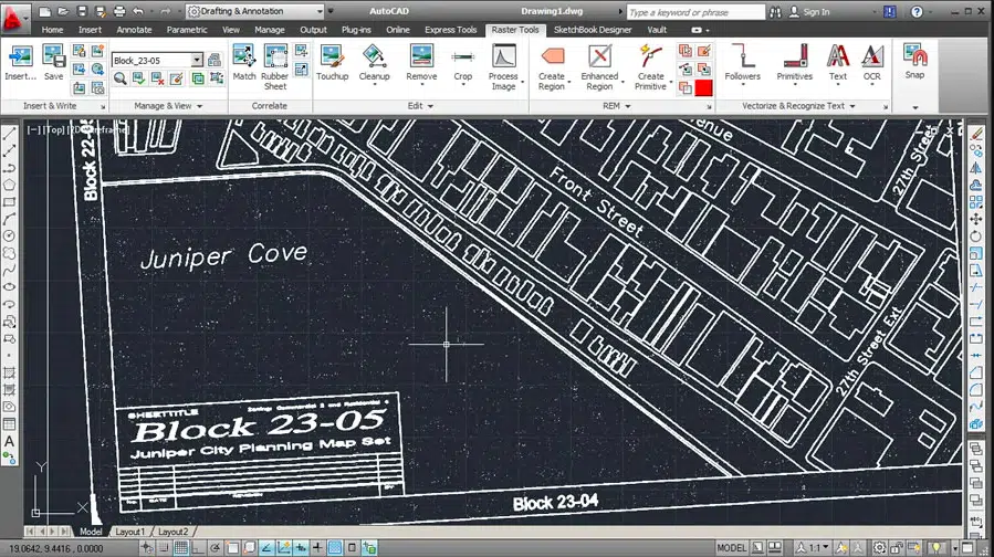
Locate the Insert tool on the far left of the Raster Design Ribbon Tab. This tool lets you navigate to the image that you want to insert into the file. You can also opt to execute the command using the command line and typing in “INSERT”. This is a bit of a departure from the usual AutoCAD command of “ATTACH” so be mindful not to get confused.
After executing the command, an Insert Image dialog box will open up. Here, you can browse for your image, but also take note of the tick boxes at the bottom. “Insertion wizard”, the default choice, will give you various guided prompts for you to personalize the insertion of the image. If you’re good with the default settings of the Insertion Wizard and don’t want to waste time going through the individual prompts, you can opt for the Quick Insert tick box.
The first thing you need to adjust after exiting the dialog box is the position and scale of your inserted image. Use the Scale command to accurately change the size of the image or simply drag one of the corners of the image to adjust its scale. You can move it using the Move command.
Editing and Cleaning up Inserted Images
Color
Raster Design works best when working with black and white – bitonal – images. Some of its tools in fact only work on bitonal images. To turn an otherwise colored inserted image black and white, click on “Process Image” on the Ribbon tabs. On the drop-down menu, click “Change Color Depth” and then type in the letter B in AutoCAD’s command line to choose the Bitonal option of the tool.
A common operation that needs to be done when converting images to black and white is to invert the resulting colors from the Process Image process. Simply click on the “Cleanup” tab and on the drop-down menu, click “Invert”.
Despeckle
Most scanned copies of plans or drawings will have speckles all over the drawing. The older and more deteriorated the physical copy of the drawings or the lower the quality of the scan, the more apparent and prolific the speckles are. But these can easily be cleaned up on Autodesk Raster Design.
Look for the “Cleanup” option in the Ribbon Tab and choose “Despeckle” from the drop-down menu. The command prompt will then ask you to specify the area that you wish to despeckle with the options “entire Image”, “Clip region”, “Polygon”, “Existing”. Afterward, specify the size of the speckle and the program will find similarly-sized blemishes and clean them up out of the image. Pick within a speckle to make a selection and then any speckles that fit the parameters you set will be indicated in red. Accept the selection when you’re satisfied with it and you have an image. Do note that depending on the speckle sizes, the program might erase things such as dots, periods, or punctuation marks that look like speckles. Just be wary of this when making your selections and the operation should run smoothly.
Manual Clean-Up
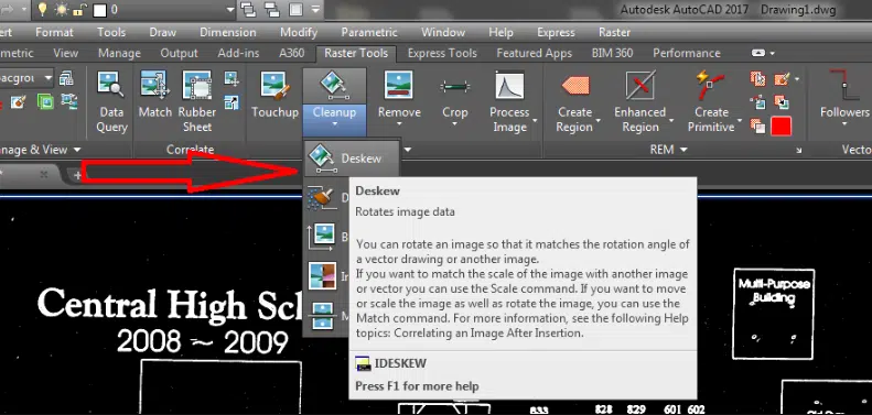
Selecting Deskew in Autodesk Raster Design (source)
Even with the advanced editing options in Raster Design, there will always be the need for manual fine-tuning. To do this, use the “Touchup” tool to manually add or take away sections of the inserted image. The use of the tool will be similar to the tools used in Microsoft Paint, so if you’ve ever had the chance to play around with that program, you’ll have an easy time using Touchup. The different settings of the tool are as follows:
- Color: switch the color of the Touchup tool from black to white or vice versa by clicking “Toggle drawing color”
- Shape and Angle: you can control the shape of the brush used by the Touchup tool by playing around with the options on the left of the toolbar. You can change the angle of the brush as well.
- Size: The fourth option from the left of the Touchup toolbar controls the size of the brush.
Once you’ve done your edits, exit the tool by using the buttons on its toolbar. You can choose “Cancel” to exit without executing the changes you made or Ok to exit and push through with the edits.
Converting to Vector
What truly makes Raster Design such a useful add-on is its ability to convert pixelated lines into vectorized, AutoCAD ready objects, this process is sometimes referred to as ‘Object Recognition‘. Click on the “Vectorize & Recognize Text” button on the Ribbon Tab and then click the “Primitives” button. The drop-down menu will have options to recognize lines, polylines, rectangles, circles, and arcs.
Align your cursor with the line or lines you wish to convert into vector objects and if the object is recognized by Raster Design, dashes will appear on it along with a yellow arrow. Accept the recognized line by pressing Enter and the program will turn it into a vector AutoCAD line while erasing the original pixel line. Clean up any remaining pixels with the Touchup tool. Sometimes you’ll find that lines recognized and converted by this tool might not always meet at corners as accurately as you’d like. Remedy this by using the Fillet tool with a radius of zero.
After editing all the lines, you might want to convert them back into raster image lines to match with the rest of the remaining image. Do this by selecting the vector lines, right-clicking on them, and then selecting “Merge Vector to Raster Image”.
Managing the Embedded Image
When you’re ready with the final image, you might want to embed the image onto the file.
By default, AutoCAD inserts images into its files as references. That is, if you send over the file to a different machine without sending over the separate reference image, the file won’t open accurately. The workaround is embedding the image.
Locate the “Insert & Write” panel on the Ribbon and click on “Embed”. It’s that easy to embed the image into your drawing.
