First released in 1999 by Autodesk, Inventor is a solid modeling design software used for creating precise 3D models. It is mainly used by designers and mechanical engineers for 3D mechanical design, electrical systems design, sheet metal design, tube and pipe design, design documentation, simulation, visualization, data management, and collaboration.
Being a software with highly advanced functionality, Inventor has a plethora of tools and features. This may well turn out to be a problem for new users trying to understand and navigate through the software. To help you solve this problem, Scan2CAD has created this compact and comprehensive article that will familiarize you with the basics of Inventor in just one hour. We will be looking at the software’s capabilities, features, tools, and user interface. We will also be looking at the basics of sketching and modeling on Inventor.
Table of Contents
What are the capabilities of Inventor
Before you begin to learn how to use any software, you must know what it can do. The capabilities of Inventor can be classified as follows; modeling, simulation, visualization, and collaboration. With Inventor, you can create 3D models of either standalone objects such as a cup, or components of an object. You can also create an assembly of the components created. For example, after designing individual components such as a piston, a crankshaft, and some valves, Inventor allows you to assemble these parts into a modular motor engine, with each of the components still retaining their individual properties. In addition to these, you can also create working drawings (drafting documents) of your finished designs. These drawings may contain orthographic projections, isometric views, part lists, and a title block. Furthermore, you can create a presentation document of your finished model. This presentation is used exclusively for creating exploded views of the model.
Using Inventor simulation features, you can run various analysis such as stress and motion, on your model. This feature is essential when you are designing for manufacturing.
To enable you to visualize your model as realistically as possible, the visualization features of Inventor allow you to explode, animate, and render your model. Rendering makes your design take on as realistic an appearance as possible.
Finally, you can easily share your finished designs with others for review and comment.
Before you get started
Before we take a look at the interface of Inventor, let us familiarize ourselves with some basic concepts in Inventor. Inventor has four primary file types and one secondary file type. The primary types are Part file (individual components) with the .ipt file extension; Assembly file (assembled components) with the .iam file extension; Drawing file (drafting document) with the .idw or .dwg file extension; and Presentation file with the .ipn file extension. The differences between these file types were stated earlier. Although these file types are different, they are usually related. In Inventor, all file types that are associated with a model are stored together in a single project folder and as a single .ipn project file.
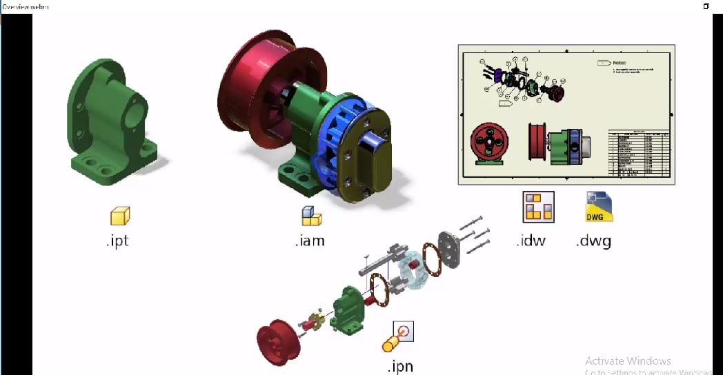
The file types of Autodesk Inventor
User interface
When you launch Inventor, you are first introduced to the launch screen. The launch screen is a somewhat familiar Autodesk software interface. It is roughly divided into three, with a menu bar located at the topmost part of the screen. On the right side of the screen is the project area. Under the heading, Project, you’ll find a list of all existing projects on your computer. Clicking on an existing project activates all the file types that are a part of that project. Note that a file cannot exist outside of a project. Therefore, if you want to open an existing file, say a part file, you need first to activate the project in which it is contained.
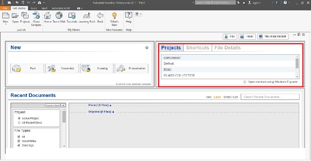
The Project area of the launch screen
On the left side of the launch screen is the New area. This area contains thumbnail links of the four primary file types. Clicking on any of them would open the corresponding interface for you to begin modeling. Recall that any file type you open would automatically be stored under the currently activated project. To open a new file under a new project, you have first to create the new project. We will explore how to do this later on in the article.
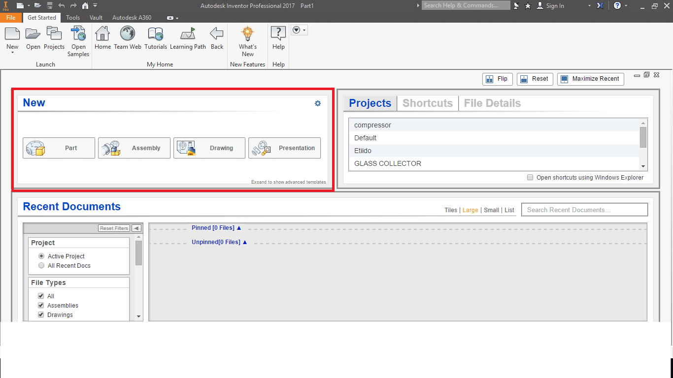
The ‘New’ area of the launch screen
At the bottom of the launch screen is the Recent documents area. This is where all recent files, whether part or assembly, can be accessed. You can filter this area to show only the recent documents of the active project.
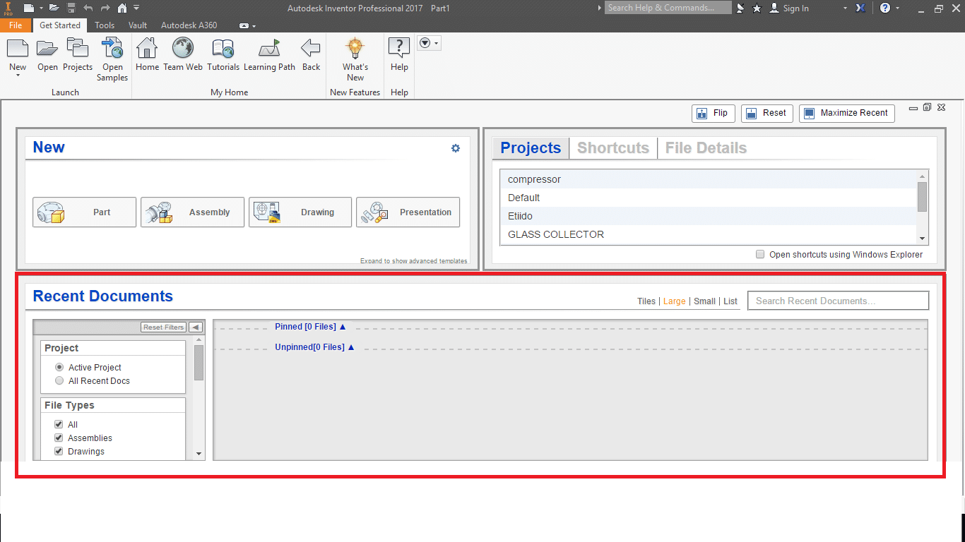
The ‘Recent Documents’ area of the launch screen
The menu bar is located at the topmost area of the screen. It contains several useful links to tutorials, Autodesk news, Autodesk Vault, Inventor learning path, and Autodesk A360. You can also open a new or existing project from the menu bar.
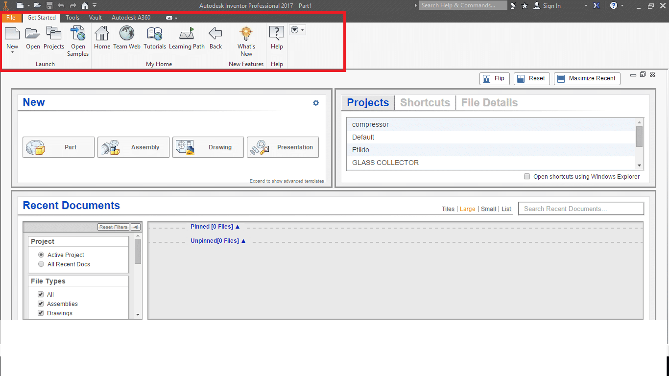
The Menu Bar
Getting started
The different file types in Inventor have different interfaces. This means that the graphical user interface (GUI) for creating an assembly is different from the GUI for creating a presentation. A part is typically the first thing you need to create before you can create an assembly, a drawing, and a presentation in that order. Therefore, since we are dealing with the basics, we will be exploring only the part creation interface.
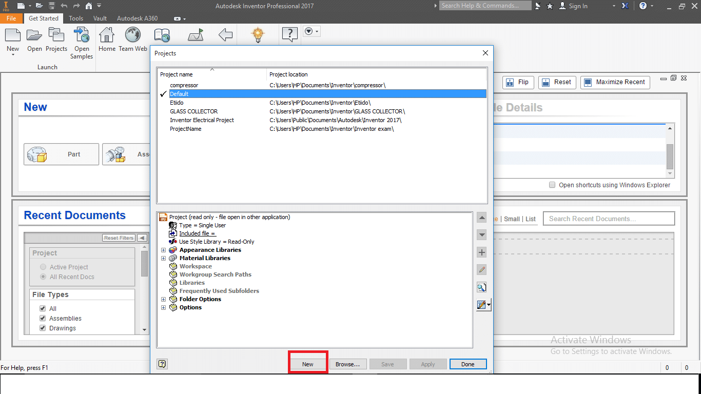
As discussed earlier, you can only create a part as part of a project. For this tutorial, we will be opening a new project. To do this, click Projects in the menu bar and select New at the bottom of the dialogue box that opens.
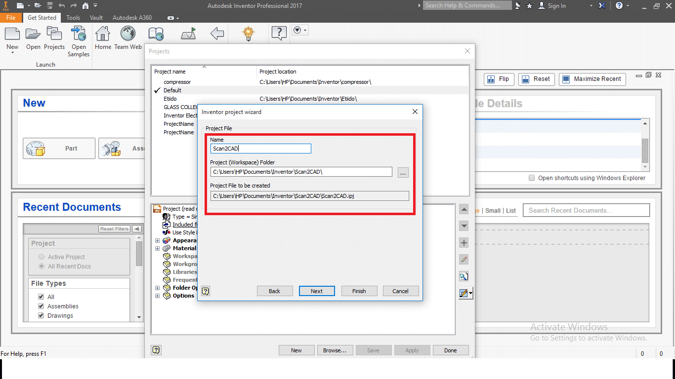
This will lead you through a few simple processes in which you can name and select the location of your project. We will name our project, Scan2CAD. Once you finish creating it, the project becomes active in the project area of the launch screen.
Any file type we create now will be part of the Scan2CAD project. We can now proceed to create a part. Inventor supports many drawing standards including ANSI, ISO, BSI, JIS, GB, GOST, and DIN. The software also supports both the metric and imperial systems of measurement.
There are two ways to open the part GUI, and both ways require you to select your preferred standard and system of measurement. The first way is to click on the corresponding icon in the new area. However, this automatically opens a part file in the default standard. To change the default standard, click on the small settings icon in the new area and select your preferred standard before proceeding to click on the part icon.
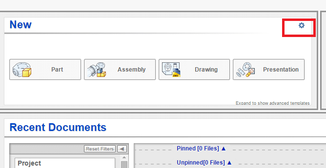
The settings icon for creating a new part
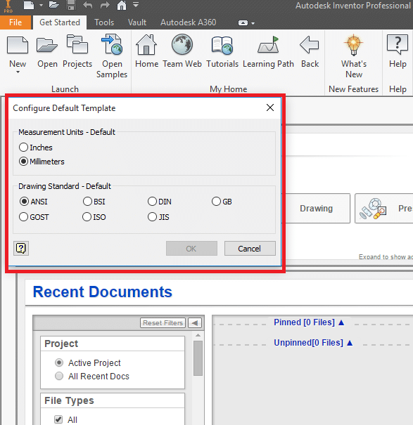
Configuring the ‘New Part’ template
Another way to open a new part file is to click on the open icon on the menu bar. This opens a dialogue box that displays all the file types in all the available standards. You can then select the file type and standard you prefer. This leads us to the part GUI. Note that these processes are the same for any file type you wish to open.
Main graphical user interface
As discussed earlier there are four different GUIs for the four primary file types, but we will be focusing on the part creation GUI.
Part creation GUI
The screen is roughly divided into three. The ribbon, the project browser, and the drawing area. The ribbon itself is divided into two, the menu bar and the quick access toolbar. The quick access toolbar contains some commonly used commands and tools such as redo, undo, open, save, etc. It is located just above the menu bar. You can easily add new file types to the open project.
The menu bar contains all the features, tools, and settings required to model, visualize, simulate, and edit a part. Similar tools are neatly organized into panels. The panels themselves are organized into tabs of different headings.
The first tab is the Sketch tab. The design of a model on Inventor typically beings with a sketch. The tools under this tab allow you to create sketches using four fundamental shapes; line, circle, arc, and polygon. The Sketch tab also contains tools to modify your sketch, add patterns, add dimensional or geometric constraints, and import images and .dwg file into Inventor.
The next tab is the 3D Model tab. The tools in this tab are dedicated to turning your sketch into a solid 3D model. You can extrude, revolve, sweep, loft, add patterns, create a free-form, and insert holes. You can also emboss, fillet, changer, thicken, and cut threads. This tab contains the bulk of Inventor’s modeling features.

The 3D Model tab
The View tab comes next. The tools in this tab not only apply to your model but also to the entire GUI. You can change the look of your design from wireframe to realistic or shaded. You can also create textures and orthographic views. For the GUI, you can clear the screen, change the arrangement of the user interface, and switch windows. Finally, the navigation tools required to zoom, pan, and orbit a model can be found under the View tab.

The View tab
After the View tab comes the Tools tab. This tab is similar to the Options tab in various other software. This tab allows you to apply and edit numerous application and document settings. It also allows you to adjust the material and appearance of your model. For example, you use wood or metal. Inventor has hundreds of applicable materials.

The Tools tab
Other tabs and their features are as follows
- Get started tab – Contains the same tools that are in the menu bar of the launch screen.
- Analysis tab – For carrying out thorough analysis and simulation of your model.
- Environment tab – To create molds, arrange your model for 3D printing, convert your model to sheet metal, exchange data with AutoCAD, and analyze the eco-impact of your design. This tab also contains a link to Inventor studio where you can render and animate.
The second portion of the screen is known as the Project browser. It is located on the left side of the screen and contains the history of the model you are creating. For example, you create a model by sketching a square, extruding the square into a cube, placing a hole in the cube, and threading the hole. TheseThis steps would be displayed on the project browser as the following headings; origin, extrusion, hole, and thread. To edit any step, simply click on it in the project browser and you will be able to modify it. For example, if you wish to increase the length of the extrusion of the cube, you do not need to undo the thread or the hole. You can simply click on the extrusion step in the browser and edit the values. All following features will immediately adjust to the new settings. This is a very convenient and intelligent feature of Inventor.
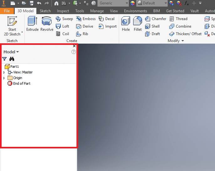
The project browser
Centrally located on the GUI is the drawing area. The drawing area is the canvas on which you will carry out your drawing, modeling, detailing, visualization, and simulation. It displays your model as it is. The drawing area is like an application window within an application, and like most application windows, it has the close, minimize, and resize buttons. Therefore you can resize the drawing area, minimize it, or close it without closing Inventor.
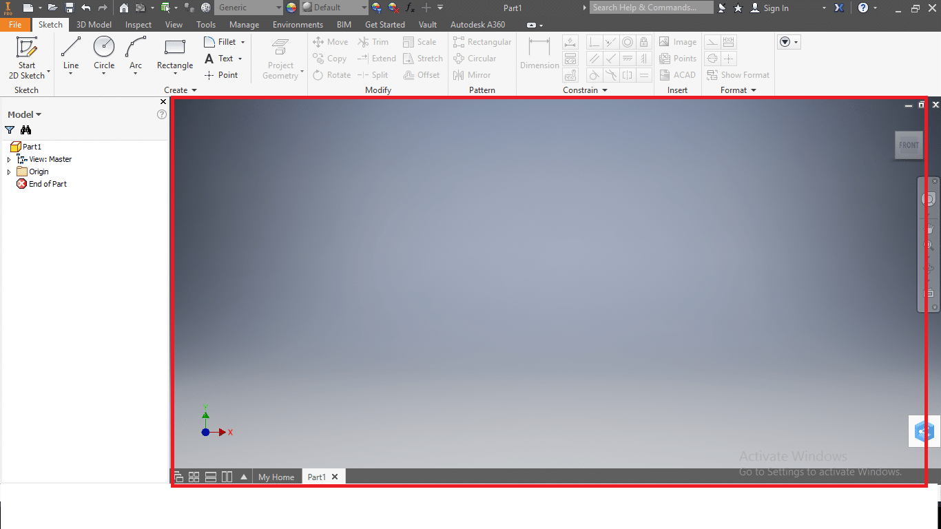
The drawing area
If you are working on more than one file at once, they are docked as tabs at the bottom of the drawing area. Note that it is possible to part, assembly, drawing, and presentation files for the same all at once. You can easily switch between their GUIs by clicking on the corresponding tab at the bottom of the drawing. Since they belong to the same project, any change made in a part is reflected in the assembly and also the drawing.
Drawing and modeling
Now that we have familiarized ourselves with the Inventor interface let’s get to the modeling proper. Any model, no matter how complex, begins with a sketch. To begin a design in Inventor, click on Start 2D Sketch. You’ll be directed to select between three planes, YZ, XY, and XZ. Next, select any of the sketch shapes and proceed to click on the drawing area. Move the mouse to determine the length of the line or circle and click again. Go back and forth between the create panel and drawing area until you produce a shape. Click on finish sketch to activate the 3D modeling features with which you can extrude, add holes, fillet, and many more.
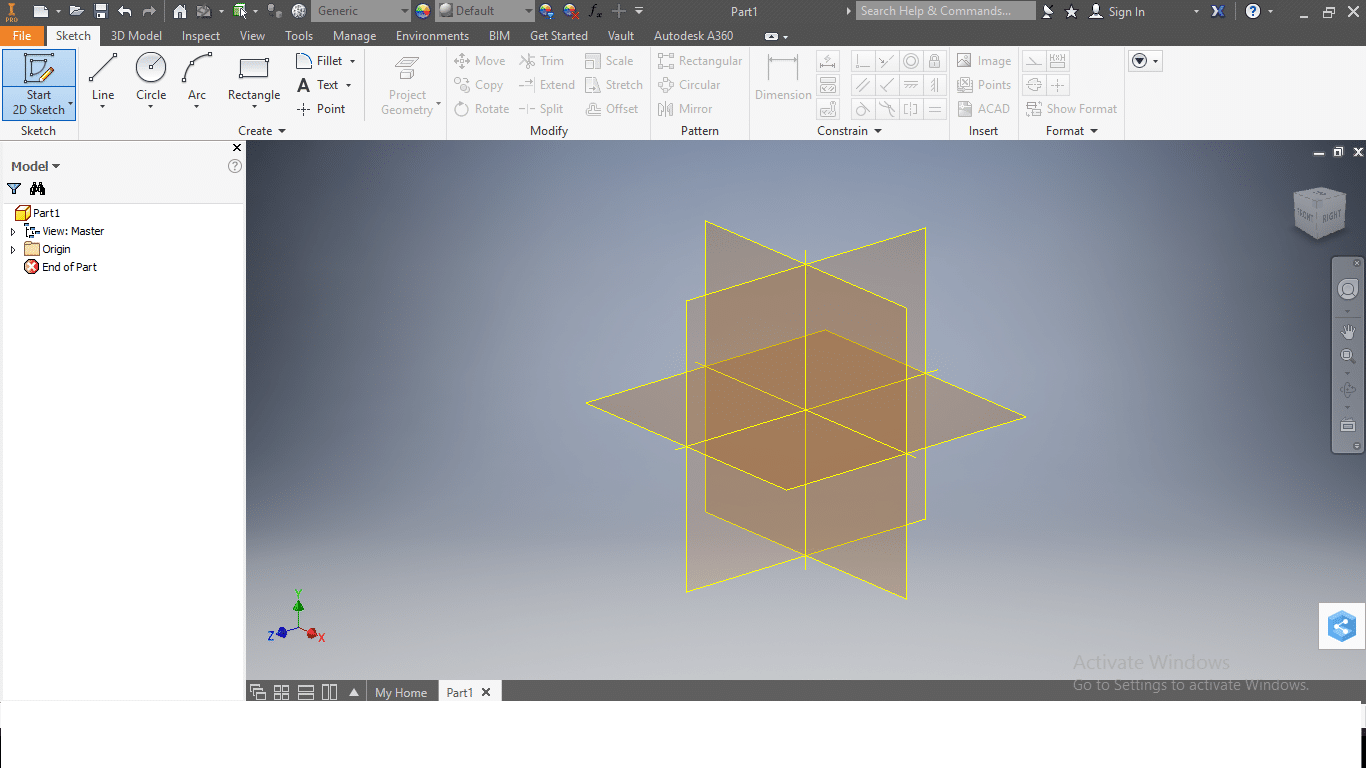
Available planes in Inventor
Recommended resources
Being such an advanced software package, Inventor has many features to be learned and is mostly used by professionals. This article has covered the basics that will serve as a rock-solid foundation for your journey to Inventor mastery. The following links contain more extensive tutorials that will help you become an Inventor professional.
