Table of Contents
About Solidworks
Solidworks is a 2D and 3D capable CAD program that most designers and engineers will be at least familiar with. It’s a household name in 3D modeling technology and its primary market is the manufacturing and mechanical design niche. It also has a lot of users in the construction and design industry.
The main appeal for Solidworks is its top-down design approach when it comes to CAD work and 3D modeling. The user typically starts with a 2D sketch oriented on a plane of their choosing. This sketch is made up of lines, splines, points, arcs, and other parametric geometric objects. Values that determine their various attributes such as length, radii, and tangency in relation to other objects drive the appearance of the geometry.
On importing images

The Solidworks interface. Source: solidworks.com
With the top-down workflow incorporated into Solidworks, users will inevitably find themselves having to import 2D plans or sketches into the program to be used as references. Sometimes these reference images will be scanned copies of floor plans and details or hand-drawn sketches of details. There could even be actual scans or photos of patterns or gaskets that need to be imported into the program for CNC work.
With any imported image, the most important factor is the clarity of the image and the accuracy of the measurements as well as the dimensions, seeing as the end goal of a lot of these processes are workable 3D models that will sometimes be used to prototype certain machine parts using 3D printers or CNC machines.
There’s a straightforward way of importing your image into Solidworks, and that’s through the Sketch function. Just import your image file, a step that should be a breeze if your image file is in a format that Solidworks supports, and trace over the image.
For simpler images, Solidworks has an automatic tracing tool that should generate sketch lines that go over the outlines of the image. But this only usually works for images with solid edges and outlines. Automatic tracing would be harder to do for, say, full-blown technical images or physical photographs of objects.
Luckily, you can use all the sketch tools in the program to just trace over the imported image manually. For simpler geometry, this would be easy, but some challenges might arise when you’re working with machine-accurate objects or anything that has very little room for error.
Even though Solidworks’ own automatic tracing tool might not be able to handle them, there is third-party software, such as Scan2CAD, that can manage the raster-to-vector conversion process before importing the image into Solidworks. That way, you’ll be dealing with an imported and editable vector file rather than a raster image which you still have to trace over. This is recommended for more complicated images or if manually tracing over seems too tedious of a job.
We’ll be going over all of these methods in this article.
Raster and Vector images
Let’s try to cover the basics of these terms and file types first before diving into particulars. Raster and vector images are what we’ll be working with when trying to trace an image on Solidworks. Those are the two main categories of images that we want to discuss.
Raster images – also called bitmap images – are made up of colored pixels clustered together to form images. The typical image files we deal with such as JPG, GIF, and PNG are all examples of raster images. The clarity and quality of these images depend on their resolution. Simply put, the larger the file and the more colored pixels or dots per inch of the drawing, the better the quality. Ideally, we want high-quality images for Solidworks. Blurry, pixelated copies will still work, but, as we mentioned before, accuracy is important when doing this and that just isn’t guaranteed with low-quality images.
Vector images, on the other hand, are generally easier to work with on Solidworks since they’re fully editable by the software. In fact, some output files made by Solidworks and most other CAD software are considered vector files. Their main difference between raster files is that instead of being made of pixels, they’re made of formulas and instructions detailing the look and size of specific geometric elements.
If it’s still a bit confusing, imagine a picture of a black line. If this were a raster image, the file would be made up of black pixels clustered together to form the look of a black line. If this were a vector image, the file would be made up of instructions on the color of the line, the thickness and length of it, and its orientation or angle.
So when it comes to dealing with raster and vector images, we prefer working with vector ones for most CAD programs.
File formats for Solidworks
Solidworks file-formats. Source
Next, let’s move on to discussing what kind of image files and formats can actually be imported into Solidworks. It’s a pretty extensive list that covers the more common file types.
|
For Import |
|
|
Sketch Picture |
|
|
2D Paths |
|
|
3D Mesh |
|
|
3D Solids |
|
|
CAD and Vector |
|
|
Special Files |
|

Tracing using Solidworks tools
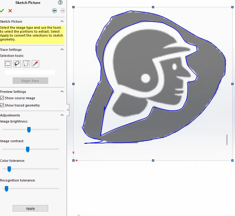
Solidworks auto-trace function. Source
Uploading your raster image or photo onto Solidworks is a simple enough process. Although at the end of it, you’ll have to decide if you want to trace over the image manually or if you want to use the auto-trace add-in to do the tracing for you. We’ll go over into it in more detail later on.
- The first thing we want to do is figure out the plane on which we’ll be inserting the image. You’ll want to pick the Top plane if you’re working with a plan drawing, the Right plane if you’re working with a side detail, and the Front plane if it’s a front-facing detail.
- Once you click on the plane you want to work on at the left side of the interface, create a sketch. Once you’ve started the sketch, click on the Tools drop-down menu and choose Sketch Tools. From there just click on Sketch Picture.
- Here’s where you pick out your picture. Before we go on, let’s go through some photo quality basics.
If you’re converting an image of a physical object it’s important that you acquire a suitable image in the first instance. Here are some key tips:
– Take a photograph of the object on a contrasting background.
– Ensure the camera is perfectly parallel to the object. You can achieve this by taking a picture from afar with a zoomed-in lens.
– Ensure there is appropriate lighting so there are no shadows or shades. Excessive shadows sometimes make it harder to figure out where the edge of the object is.
– Take a high-resolution photograph in a lossless format. Go for TIFF or RAW since JPG is notorious for compression.
Ideally, we would recommend scanning the object using a flat-bed scanner (the same used for paper) for the best results.
- Resize the image as you see fit. First, try to get it to fit into the work area, so scale up or down as you need. Afterward, you can try to refine the scale by finding a part of the drawing whose measurement you have verified. Then you can sketch a measured line with a similar dimension somewhere to use as a reference. Then all that’s left is to try and manually scale the image using the line you sketched.
- Now comes the actual tracing of the object. You can choose to do it manually using the Sketch drawing tools that Solidworks has, but you could also try to use the Auto-trace add-on function.
Using Scan2CAD
Manual tracing on Solidworks is great for simple images, but it gets more difficult for larger or more complex drawings. Additionally, the auto-trace function in Solidworks won’t always work with certain images. So this is when conversion software like Scan2CAD comes in handy.
Let’s go through the step-by-step process of converting raster images to vector files using Scan2CAD and opening them up on Solidworks.
- Open up the raster file you need to convert on Scan2CAD.
- We have tons of tutorial videos to help you out with the actual process, but the gist of it is to clean up the image first, turn it monochrome, and then go on with the actual conversion. All of this can be done in Scan2CAD and has a much more dynamic and customizable user experience than any auto-trace functionality.
- Importing the resulting vector file is just a matter of opening up the file on Solidworks. There are a bunch of options you have to configure when opening up DWG or DXF files, but most of these have to do with layers and visibility which we don’t have to worry about since the file was converted by Scan2CAD. So just go ahead and open up the file.
