As you may already know, DraftSight is a popular freemium 2D CAD product used across a multitude of industries including architecture, design and engineering (it is a popular alternative to AutoCAD). With it, you can create 2D models not to mention access and edit DWG files. But did you know that you could also trace using DraftSight? While it doesn’t offer automatic tracing capabilities, it is possible to manually trace an image.
Interested? Scan2CAD has put together a guide to show you exactly how to manually trace an image using DraftSight. We’ve also describe how you can automatically trace your image using Scan2CAD!
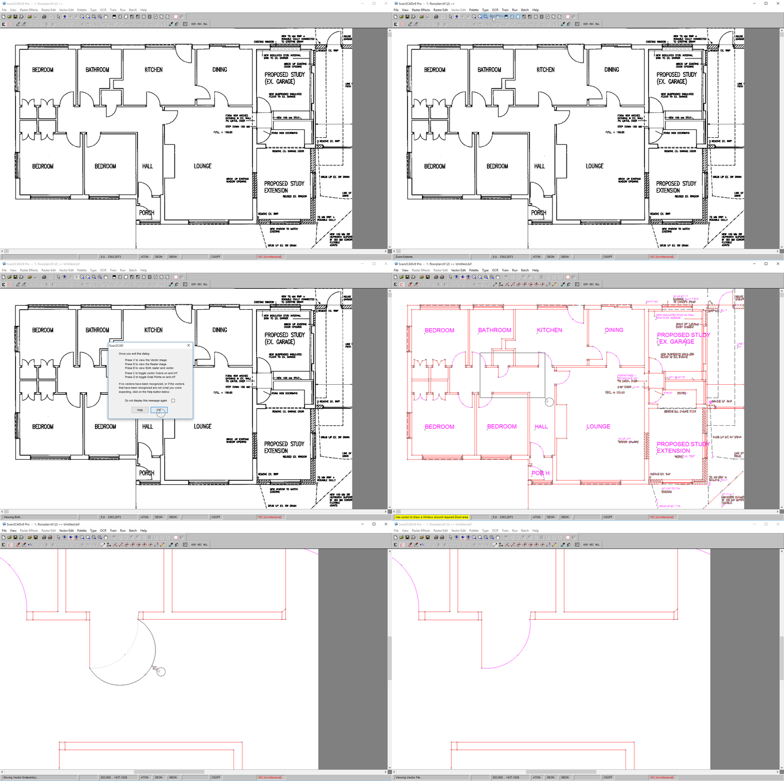
Automatic Tracing: Converting an architectural drawing (TIFF) to a vector CAD format (DXF) in Scan2CAD
What is tracing?
Tracing is the process of drawing over a raster image with vector lines, and other vector entities such as beziers, polygons, text strings and so on. This then gives you a vector output. So, what’s the difference between raster and vector files? To put it simply, vector images are much more suitable for CAD.
Raster images—like JPEGs and PNGs—are mostly used for photographs, they are programatically simple to create and display since they are effectively a grid of color blocks. They’re not always ideal, however, as they come with many disadvantages. When you want to make changes to a raster image, any edits you make will be made to the entire image. Essentially, it’s like painting over the whole image, instead of altering specific elements. Additionally, rasters are made up of pixels which affects the quality of the image when you try to resize it. This means that rasters are resolution dependent.
In contrast, vector images are mathematically perfect. They’re made up of paths, which means that you can scale the image up and down as much as you’d like without impacting the quality of the image. In other words, vectors are infinitely scalable. Meanwhile, it is possible to edit each individual element within a vector image without impacting on the rest of the image. Each element can also contain masses of data, making vector images perfect for CAD work, which often involves creating designs which replicate real-world objects.
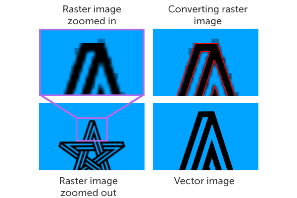
Tracing is the process of identifying objects within the image and converting them to their appropriate vector entity.
When would I need to trace an image?
Vector files are the industry-standard format in CAD. By using vectors, you can edit individual elements and re-use them when you start a new drawing. If you have a raster image that you want to use in CAD software, you can trace it to convert it to a vector. Similarly, if you have an old technical drawing, you can scan it and convert it to a vector.
If, for example, you work in architectural design you may wish to assign co-ordinates and real-world measurements to a vector element such as a line representing a wall. This is all possible with industry standard vector file formats such as DXF and DWG.
How does the process work?
You can choose to trace manually or automatically. As the name suggests, manual tracing involves drawing over a raster design by hand. This can be done with your computer mouse or with a graphics pen and tablet. It can be a time-consuming process, which is why many opt for automatic tracing instead. This process is enacted with conversion software which detects the shapes and lines of your raster and redraws them as vector entities.
Not sure which method is right for you? Check out our article on manual and automatic tracing.
What is DraftSight?

While SolidWorks supports both 2D and 3D, DraftSight focuses only on 2D, which eradicates any competition between the two products. It has an easy-to-use interface for those familiar with CAD software. And, with a relatively easy learning curve, it’s of no surprise that DraftSight is such a popular CAD product.
Manual Tracing using DraftSight
Whether you’re a regular user of DraftSight or you’re debating using it, you might have wondered if it was possible to use it for tracing. The answer is yes—it is possible to manually trace an image with DraftSight.
- Import your image. Click Insert > Reference Image. For a better look, you might have to zoom into it.
- Open a new layer. You’ll want your trace to be in a new layer in case you make any mistakes.
- Trace over your image. Using drawing tools such as line and arc, you can trace your reference drawing.
- Delete the original layer. Once you’re happy with the trace, you can delete the layer below.
- Save your image. You can save your trace as a DXF or DWG—it couldn’t be simpler.
Of course, there are setbacks to tracing in DraftSight. One of the main issues you’ll face is scaling. If you’re looking to print in a PDF format, for example, you’ll find that DraftSight can occasionally export off-scale. Additionally, you’ll have to ensure that your original image is at the right angle and aligned before you can even import it into DraftSight.
What About Automatic Tracing?
If you’re a hobbyist, or you have a very simplistic design which you need to convert then you could survive by manually tracing your image using Draftsight.
However, if your line of work requires you to regularly convert designs or if your designs are more complex than a few simple shapes you would greatly benefit from automatic image tracing.

Here’s a floorplan — before and after conversion! We’ve used Scan2CAD to convert it from a scanned image (left) to an editable vector (right), and saved it as DXF
We recommend that you learn the difference between general raster to vector conversion software compared to a specialised solution for CAD. Scan2CAD is conversion software for CAD/CAM & CNC. This specialized solution uses shape recognition to identify raster elements in your design converting them to their appropriate vector entities. With shape recognition dash-lines will be converted to vector dash-line entities, arcs will be converted to vector arcs and so-on.
Scan2CAD offers unique conversion presets for all types of technical drawings. Whether it’s an electrical plan, a CNC drawing or a contour map, you’re going to get a unique trace that takes different variables into consideration.
Automatic Tracing Using Scan2CAD
Scan2CAD is a market-leading raster-to-vector converter. It specializes primarily in the conversion of technical drawings. As we mentioned in the above section, Scan2CAD comes with vectorization settings that ensures its automatic trace is specifically catered to the type of image you’re converting.
With a full raster and vector editing suite, you don’t have to worry about the many problems that plague raster images as highlighted below:
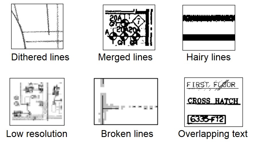
Scan2CAD’s ‘Raster Effects’ help you avert the the problems caused by poor quality images.
The process couldn’t be simpler with Scan2CAD. The software detects the lines and edges of your raster image and then redraws them using vector lines, shapes and text. It takes into consideration aspects like line weight, angles and even the type of line. By using pre-programmed variables that control how the conversion is enacted, Scan2CAD ensures you get a precise conversion. And with capabilities like batch processing and smart OCR, you can convert hundreds of images in next to no time at all.
As with many software packages out there, you can try out Scan2CAD with a free trial. But don’t worry—it doesn’t come with any limitations. This means that you can convert your images without the worry of watermarks or a conversion limit. Don’t settle for anything less than the best—start your free 14-day trial with Scan2CAD today.
Want to stay updated on all things CAD, CAM and CNC-related? Check out Scan2CAD’s blog covering topics ranging from generative design to building information modeling to Autodesk software compared.

