Preparing a drawing for CNC machining may entail a lot of work. Depending on the approach you choose, it may take anywhere between a few hours – when you use the automatic route – and several days – when you utilize the manual method.
Regardless of the route, one thing is always paramount and certain: the need for accurate scaling. Machined components, created from drawings, usually serve a specific function and are more often than not part of a larger machine/device. As such, they should fit snugly with other components of the system. And if they contain holes, then the hole patterns should align with the respective connectors in the adjoining parts.
In this article, we will discuss how you ensure that such drawings have accurate scales, dimensions, and units. Specifically, we will look at converting DXF to G-code with accurate scaling.
Table of Contents
What are DXF and G-code?
Created by Autodesk in the early 1980s, DXF or Design eXchange Format is a file type that stores vector graphics. The idea behind its creation was in order to facilitate the exchange of data between Autodesk’s AutoCAD and other CAD or between CAD programs and downstream CAM/CAE programs.
On the other hand, G-code is any programming language/code that issues instructions to the CNC milling or machining tools. G-code, therefore, tells CNC machining tools the type of actions to undertake.
Designing for CNC
When it comes to creating designs that are to be turned into actual objects through CNC machining, the process normally follows a few common steps. First, a designer sketches a freehand design on a piece of paper. Using it as a guide, they then create the design using CAD or CAM software. If the drawing is created using CAD software, then it would be stored as a DWG file. Conversely, if the designer uses CAM software, then they would save the design using the DXF file format.
The second step would typically entail converting the DWG or DXF file to G-code. This would involve importing the DWG or DXF file into a CAM/CNC software to generate the G-code. Notably, though, you can bypass this second step by again using Scan2CAD.
Alternatively, the designer can manually trace an image to generate a vector layout, which they can then save as a DXF file for importation into a CAM or CNC program. Notably, CAM and CNC programs convert the file into G-code, a programming language that enables CNC systems to execute machining instructions.
However, these manual methods are time-consuming.
To save time, the designer may opt to convert an image to DXF or DWG using Scan2CAD. In fact, as the world’s leading conversion software for engineers and designers, Scan2CAD goes beyond simply facilitating the conversion of images to DXF or DWG file formats. With this software, you can convert an image directly to G-code.
Scan2CAD automatically converts drawings stored as images or raster PDF formats into DXF or DWG or even G-code format such as .CNC.
Tips to Consider When Designing for CNC
In an earlier guide, our experts shared 8 tips you need to take note of when designing for CNC. These tips include:
- Defining the scale
- Cleaning up the CAD drawing before importing it into CAM by reducing vector lines to the lowest number of nodes that will not affect quality, placing your geometry on one layer, and exporting only the relevant parts
- Converting arcs and splines to polylines
- Deleting spaces and cavities
- Combining adjoining polylines into one entity
- Removing overlapping lines
- Setting the default Z-axis value
- Understand the cut width of the machining tool
Regarding the first tip – defining the scale – our experts recommend that it is crucial to set the system units to millimeters and the precision/tolerance to 0.5 micrometers for precision CNC work.
As a follow-up to the earlier guide, this article is designed to offer you additional information regarding the first tip. Specifically, we will focus our attention on converting DXF to G-code with accurate scaling.
Converting DXF to G-code with Accurate Scaling
Video Tutorial: Converting DXF to G-code with Accurate Scaling
Step by Step Guide
- Import the DXF file into Scan2CAD.
- Delete unnecessary objects in the imported file, including some dimensions.
- Click the File tab, and on the resultant dropdown menu, select Scale Options.
- On the resultant pop-up window, click Measure, which creates a Measure and Scale toolbar on the screen’s right-hand side (RHS).
- Click Calibrate on the RHS toolbar. Also, ensure you have checked the Snap to End Points to simplify the measuring process.
- Place the cursor at the beginning of a reference line/dimension line, whose length and units you already know. Next, click and drag the cursor to the line’s other endpoint. This step allows Scan2CAD to measure the length of the line using pixels. The software will automatically populate the Pixels field on the RHS toolbar.
- Select the units under the Is equal to the field, and input the reference line’s dimensions.
- Click Apply on the RHS toolbar to guarantee that Scan2CAD will convert DXF to G-code with accurate scaling.
- Delete the reference file.
- To save the file, click Export, which will create a Save As pop-up window. On this window, type the file name and select the file type. Notably, Scan2CAD supports three G-code file formats, namely .CNC, .TAP, and .NC. Therefore, Scan2CAD effectively allows you to convert DXF to G-code with accurate scaling by choosing any of these formats. Finally, click Save to complete the conversion.
- Clicking Save results in a CNC Export Options pop-up window that allows you to tweak a few settings. Leave the existing default settings unchanged. Next, click OK to complete the process of converting DXF to G-code with accurate scaling.
Importance of Converting DXF to G-code with Accurate Scaling Using Scan2CAD
The steps above highlight the procedure of correcting any errors that could result in wrong scales and dimensions. As stated earlier, milled components are usually part of a larger machine/device with other components requiring snug fitting. In this regard, when a converted DXF file results in wrong milling instructions, the resultant part would be rendered useless and, therefore, a waste. In addition, it would result in lost time that would need to be recovered, thereby affecting workflow. Simply put, a scaling mistake is expensive.
These factors make converting DXF to G-code with accurate scaling using Scan2CAD a critical process as it aids with the following:
- It saves time that would have otherwise been lost in preparing new G-code instructions – by converting DXF to G-code with accurate scaling – had the initial conversion not included the correct scaling and dimensions
- Furthermore, given that Scan2CAD’s tracing and conversion processes are automated, the software simplifies processes, thereby saving even more time
- It helps avoid wastage of materials by ensuring all components, once machined, fit snugly with other machined or non-machined parts
- It simplifies the process by eliminating the need for additional programs/software, some of which are extremely expensive to procure – with Scan2CAD, you no longer have to import a DXF file to a CAM/CNC software that would then convert DXF to G-code
- Scan2CAD offers additional conversion capabilities, in that you can also directly convert images to G-code or PDF files to G-code
Practical Demonstration

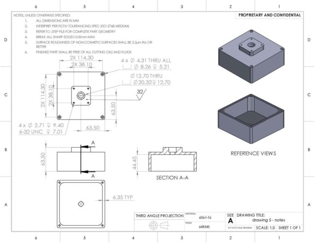
Orthographic Drawing (source)
To put each of these vital points into perspective, let’s consider the orthographic drawing above. It features dimensions that show the distances between hole positions, the diameters and depths of holes, as well as the heights, length, and width of the different parts of the component.
If, for instance, a designer forgets to set the dimensions’ units as millimeters while converting the image to G-code and instead uses centimeters, the machined component would be larger than desired. This would render the machined piece unusable because even the screws that were initially supposed to be threaded through the thru-holes would be smaller. These shortcomings would mean that the designers would have to recreate the G-code, losing valuable time.
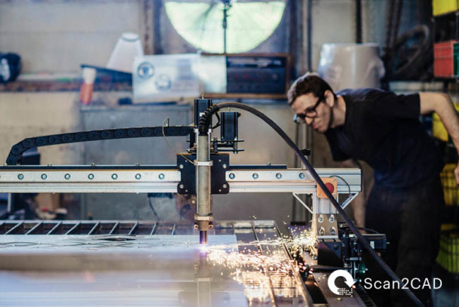
On the other hand, the machined component would either be melted to create a new, unaltered surface/material that the CNC machine will work on or discarded for being unusable. For instance, an error in the G-code, possibly in the dimensions of the cut pieces in the image below, would cause the machinist to discard the entire sheet of metal and the cut components. Naturally, melting the material takes up unnecessary resources in the form of time and energy, while discarding the piece altogether causes losses in the form of wastage.

CNC Milling Machine
Parting Shot
The importance of converting DXF to G-code with accurate scaling cannot be gainsaid. It helps avoid wastage of resources such as time, money, and materials, and as we have demonstrated, using Scan2CAD offers additional benefits. With this guide, we hope that the process of converting DXF to G-code with accurate scaling is now clear and that we have equipped you with the necessary knowledge to avoid mishaps during CNC milling.

