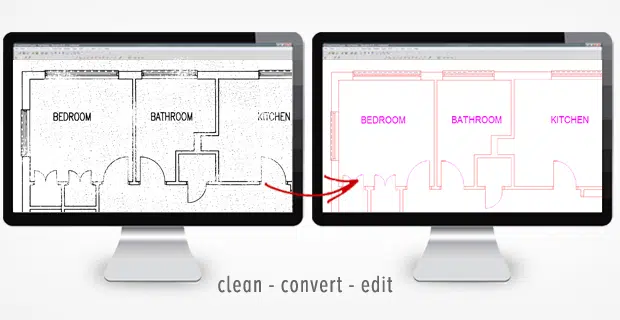

The software first ‘traces’ the image and draws CAD objects
Scan2CAD is a raster-to-vector conversion, or vectorization software. What it essentially does is trace images and create CAD drawing objects. All images are made up of different types of information, which are all captured using different techniques.
- The software first ‘draws’ all elements which create the file (Psst. You can click here to read the list of elements used to create the vector conversion.)
- There are all sorts of parameters to consider, such as the angle of the curves, line weights (either thick or thin), type of line (either centerline or outline) and so on.
- Text in images can also be captured using image conversion software. This is accomplished using OCR (Optical Character Recognition) technology.
- Certain software can also create more specialized CAD objects. For example, a GIS-dedicated software can georeference raster images with coordinates and save MapInfo.
Once the software has traced and drawn up all the CAD objects, it can then saves the drawing as a DXF file. Data is encoded according to the official DXF file specification, so that it can be read by other CAD programs.

Parameters for optimum conversion results
![]()
There are a few parameters/techniques that the software plays around with to produce the optimum vector image output:
- Smoothing, or Fit tolerance of the spline – The software can specify how smooth the output line should be like, or how closely the spline should conform to the raster image
- Compression tolerance – This setting influences the number of vertices used to construct a shape
- Corner sharpening – This parameter dictates whether your output vector image should contain prefer sharp corners vs. smooth curves
- Gap jumping – This is the process of filling in gaps in the raster image to create unbroken vectors
- Line thickening/thinning – Lines on the raster image are made thinner, until only the center of the original line remains. The software also defines a maximum line width setting to omit lines that are too thick or too thin.
- Type of Intersection – This parameter is used to define the intersection of lines. For example, you’d want to preserve right angles in an architectural drawing and set a median intersection in contour maps.
- Noise level – Most scanned images may contain speckle, dust or unwanted spots. These can be removed by defining a noise level; for example, if an outline has fewer pixels that a specified setting, the pixel is discarded and treated as noise.
- Colors – Sometimes, software also convert halftone and color images to black-and-white images for further recognition. This is because a high contrast image are easier to trace than that with low contrast. You’d be surprised that even a black-and-white drawing may end up in many shades of gray. After an image like this is converted, a single line could appear like two, because they’re in two shades of grey.
There are other techniques that you can apply before converting an image to DXF. There’s thresholding, which tidies up an image by whitening the background, while blackening the foreground drawing detail. Anti-aliasing refers to the smoothing of jagged pixel outlines. The software would add some pixels around the edges to create the illusion of a smooth line.