Scan2CAD is used throughout the CNC process — from sketch, to CAD design and finally, fabricated in CNC! This document walks you through the most common design approaches. Our experts also share 8 top tips that you should take note of when designing for CNC (scaling, overlapping objects and more!)
Before we begin…
Are you looking for free designs which are ‘cut-ready’ for your CNC projects? Check out our library of free DXF designs for CNC. We release new packs every week and they’re all free to use in hobbyist or commercial projects.
Table of Contents:
- What is CNC
- The Design Process: From CAD to CNC
- 8 Tips for Designing for CNC
- Using Scan2CAD to Convert Images for CNC
- Case Study: Reverse-engineering CNC parts
What is CNC?
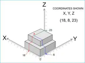 CNC stands for Computer Numeric Control. The computer converts the CAD design into numbers – graphic coordinates – which control the movement of the cutter. In the diagram on the left, the cutter is at point A (18, 8, 23). The computer-controlled cutter will travel to different sets of coordinates, in sequence, until the desired shape has been manufactured.
Some of the most common types of CNC machines…
| CNC Machine Type | Description |
| Plasma cutter | Cuts material by flying across the cutting table with a plasma torch (instead of moving a spinning tool over the material) |
| Laser cutter | A similar principle to the plasma cutter, it uses a laser. Both of these cutters are used to cut 2-dimensional profile shapes |
| CNC router | Perform complicated cutting operations like rabbeting, routing, drilling, slot cutting and threading |
| Milling machines | Cuts wood, plastics and sheet metal in 3 axes (X, Y and Z). This allows cutting of basic profiles |
From design to CNC fabrication…
It all begins as a drawing, perhaps in CAD software. The design is usually saved as a DXF or DWG – you may need to convert your image to one of these formats first. Then, you’d import your drawing into CAM/CNC software to generate the G-code which will control the CNC machine.
Tip: You can create G-Code formats from you designs directly in Scan2CAD.

There are a few ways you can create your CAD design. In the next two slides, we’ll walk you through the most common workflows.
Example 1: Manually trace an image creating the vector cut paths
We’ll start with a photograph of a tractor. Trace around the silhouette and the main features that you want to cut out. Save your design as a DXF file and import it into a CAM program to generate the G-code.

Example 2: Automatically Converting an image into DXF drawing format
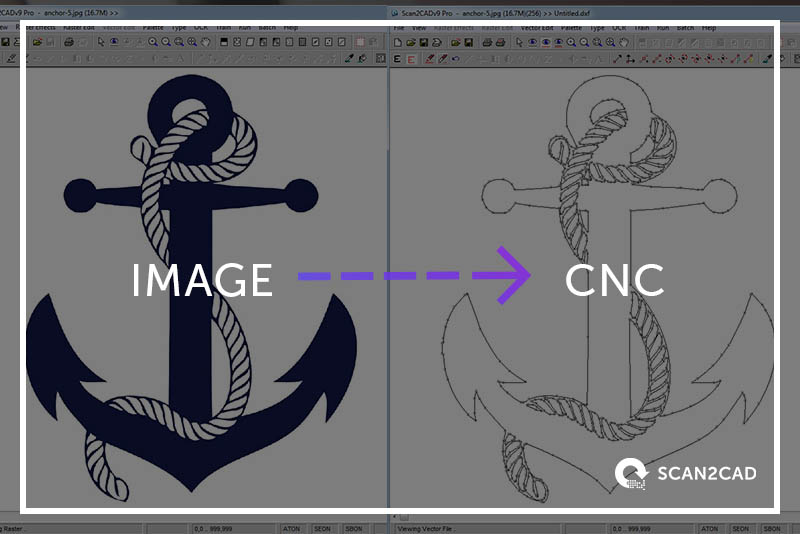
Scan your sketch and save it as a PDF or image format (e.g. JPEG, TIFF). Convert the file to DXF format using conversion software like Scan2CAD. Import the vector DXF file into a CAM/CNC program to generate G-code. In fact, you can also convert and image directly to G-code formats in Scan2CAD.
8 Tips for Designing for CNC
1. Don’t forget to define the scale of your vector image
For precision CNC work, it’s good practice to set the system units to millimeters; and precision or tolerance to 0.5 µm. Scan2CAD has three different ways to scale vectors when exporting them to DXF file format. Check out this article in our User Manual to learn more.
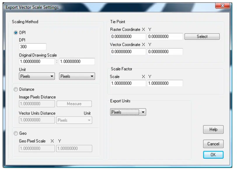
Vector Scale Options in Scan2CAD
2. Place your geometry on a single layer
After designing your CAD drawing, you should make sure it’s been cleaned up before importing it to CAM. For best results, you should:
- Reduce the vector lines to the lowest number of nodes without being detrimental to the design quality
- Only export the relevant parts of your drawing into the final DXF file
- If you need to edit in your CNC software, lock layers that you don’t want to accidentally select or move around
3. Convert splines and arcs
Many CNC machines prefer to work with polylines (i.e. many lines as a single vector entity), rather than a series of broken entities like arcs, beziers and lines. In Scan2CAD, you can convert a spline into a polyline using the vector editing tools. To do so, select Vector Edit Menu, then Modify, then Bezier to Line. Finally, click on the Bezier curve you’d like to convert.
4. Remove spaces and draw one coherent cut path
If you want clean, connected cut lines, then you must ensure that your relevant vector lines are connected. This is especially important when you turn lines and arcs into polylines. Make sure that the lines and arcs join together perfectly by using Snap tools (do not approximate!) AutoCAD users would find the PEDIT command handy for this purpose. In Scan2CAD, you can define a Grab Snap Distance between grab points.
5. Select touching objects and convert them into a single entity
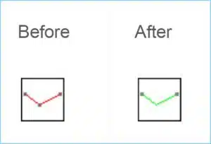 In Scan2CAD, select the Vector Edit Menu, then Modify, then Make Polylines. If there are arcs in your drawings, you must check Include Arcs before converting them into polylines. This function is found by clicking Vector Edit Menu, then Modify > Polylines Options > Include Arcs.
6. Remove overlapping geometry
If there are overlapping vectors in your design, you’re basically instructing the CNC machine to go back and forth in the same area. This is may be OK for some laser etching designs but in most cases it is not practical. Delete duplicate copies of objects. Combine lines that partially overlap (for example, arcs drawn over portions of circles) Combine objects when aligned end-to-end.
7. Set your default Z-Axis Value
In Scan2CAD, you can set the default Z value for all vectors in the CNC export options. (File > Vector > CNC Export Options) You can also set the Z value for individual vector elements should you wish to.
8. Familiarize yourself with the cut width of tools on your CNC cutting system
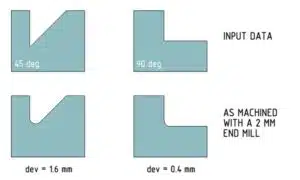 The depth and width of cut are crucial variables when milling pockets, profiling, facing and performing other machining operations. Understanding your cut width will help you control your feeds and speeds, the Material Removal Rate and how long it will take to complete the operation; as well as the surface finish. The spacing between your toolpaths should be comparable to the diameter of the tool. Also take note that machined corners depend on the size of the end mill, and this affects how to parts fit together. To learn more about CAD and milling strategies, check out this guide to Mastering CAD and CAM for CNC Machining by Michael Zalewski.
Using Scan2CAD to Convert Images for CNC
Why use Scan2CAD to prepare your CNC drawing file? You could either trace an image manually or convert that image automatically! The first option could take hours, or even days – time that could be better spent working on other things! Alternatively, you could load the image file into a raster-to-vector conversion program like Scan2CAD. A few clicks later and voilà! Out comes a DXF file that’s ready to edit in CAD software. Once the image is converted into DXF, you can easily edit it using any CAD program. The Scan2CAD vector editing toolbox offers all the basic functions:
- You can cut, copy and paste certain elements of an existing drawing.
- You can edit specific elements of the drawing, including stretching vectors, converting lines to arcs, and more.
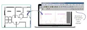
Converting your image to DXF is easy with Scan2CAD!
- Load the image or PDF file that you’d like to convert.
- Select the conversion settings. Scan2CAD comes with pre-programmed settings. For example, there is an “Architectural” option that is designed to trace straight lines and right angles, whereas the “Contour Map” setting traces curves well.
- Click “Convert”. Wait a few seconds and voilà! You have a DXF file that is compatible with any CAD software on the market. After conversion, you can choose whether to display only vector information or to overlay the original raster image as well.
- Save the DXF file. Now, you can view, edit and clean up the DXF file with any CAD program, before importing it into CAM software. Tip: You can also save in a G-code formats (.nc, .cnc. .tap)
Case Study: Reverse-engineering CNC parts
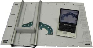 Shapemakers is an Australian CNC company that manufactures an A0-size scanning system called Deskan Color Express 6. Its clients turn to Shapemakers to scan old gaskets, drawings and seals (up to 1180x870mm in size!) The Deskan 6 software can scan the A0 drawing in strips and stitch these together using the proprietary software.
However, its clients require the drawings in DXF vector format for editing in CAD or cutting on a CNC machine. That’s where Scan2CAD comes in. Our software allows Shapemakers to vectorize their large scans and cut out the parts quickly and easily.
Grab this post as a slideshow
If you’re interested in creating parts yourself, check out our guide to the best CNC kits for beginners.
This guide is brought to you by Scan2CAD, the market leading file conversion and editing software. Scan2CAD includes conversion tools, image editing and cleaning tools, smart OCR, full PDF support, as well as vector recognition and editing. Download your free trial for 14 days, with full access to all of Scan2CAD’s features.
