
As a versatile conversion software, Scan2CAD can convert Instrument Loop Diagrams (ILDs) saved in non-CAD formats to CAD-readable formats. As one of its many capabilities, this conversion is made possible by numerous features packed into the software. For instance, it has in-built optical character recognition (OCR) technology to detect all the text within the drawing you wish to convert. But this is just one of its many capabilities. It also enables you to clean the image by removing speckles and holes, thickening lines, and smoothing the drawing.
In previous video-based and article-based tutorials, we have explored how you can use some of these features to convert a number of engineering and architectural diagrams to CAD, including Piping and Instrumentation Diagrams (P&ID) and floorplans. We have also detailed how to convert PDF to DWG with layers, as well as how to use Scan2CAD as a free PDF to CAD converter.
In this article, though, we shall focus on how to convert Instrument Loop Diagrams (ILDs) to CAD as a follow-up to our earlier tutorial on how to convert P&ID to CAD. In addition to discussing in great detail how you can go about converting ILD to CAD, we will explore the differences between P&IDs and ILDs. But first, what is an instrument loop diagram?
Table of Contents
What are Instrument Loop Diagrams (ILDs)?
To understand Instrument Loop Diagrams (ILD), let us take you back to our earlier tutorial on how to convert Piping and Instrumentation Diagrams (P&IDs) to CAD. Here, we observed that P&IDs provide a blueprint that guides installers when setting up pipes and equipment in a given plant. They describe the entire engineering design process by showing how pipes connect with each other and with other instrumentation and equipment.
Being a blueprint, therefore, P&IDs paint the big picture – they describe a process from beginning to end. But what happens when you only need a diagram that focuses on a single section or area? This is where ILDs come in.
While P&IDs show a collection of instruments and equipment, including the instrumentation controls and measurement interactions, connections, and wiring, the ILD only focuses on a single subsystem or section of the P&ID known as a loop. For instance, the ILD might focus on only a single instrument with the aim of giving a clearer picture of how that instrument connects to the other parts of the system. It might also show how instruments are arranged in the loop.
In this regard, the Instrument Loop Diagram gives a more detailed view of a loop, in effect diagrammatically explaining how the loop operates. They contain details that may have been omitted from P&IDs. Notably, ILDs are also known as loop sheets or instrument loop drawings. As is the case with the P&IDs, ILDs contain symbols defined by the International Society of Automation’s (ISA) standards, which unify the global preparation and interpretation of such diagrams.
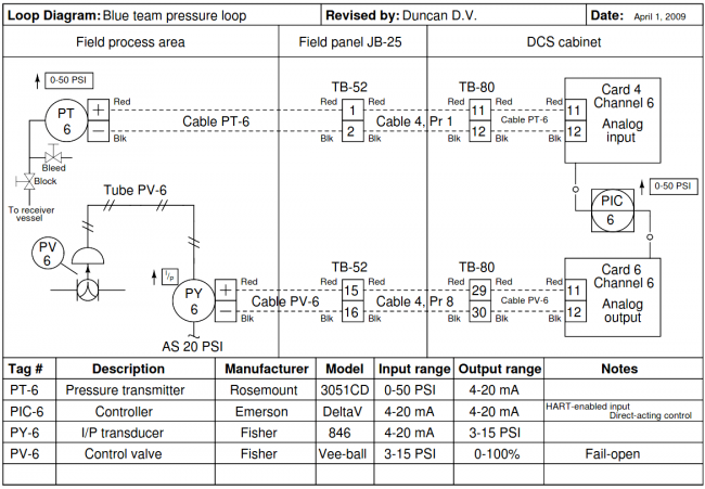
Instrument Loop Diagram (source)
Uses of Instrument Loop Diagrams (ILDs)
As stated, Instrument Loop Diagrams (ILDs) show how instruments are arranged in the loop or how a single instrument connects to other parts of the system. In this regard, you can use ILDs for the following purposes:
- To guide installation
- Troubleshooting
- Loop maintenance
- To identify the communication path between instruments as well as the connections between instruments
Differences Between P&IDs and ILDs
|
Piping & Instrumentation Diagrams |
Instrumentation Loop Diagram |
|
|
|
|
How to Convert Instrument Loop Diagrams to CAD using Scan2CAD
Best Conversion Practices using Scan2CAD
While Scan2CAD has numerous features and tools with which you can clean an image or drawing, it is advisable that you nonetheless use a high-quality image. This is because it eases the conversion by ensuring that Scan2CAD converts circles as arcs and not as joined polylines. It, therefore, reduces the time you would have otherwise used to clean the image or correct the errors in the converted image.
Simply, the higher the quality of the raster ILD, the better the converted raster drawing will be. That said, let’s discuss how to convert Instrument Loop Diagrams, saved as raster images, to a CAD-readable format using Scan2CAD.
Converting Instrument Loop Diagrams to CAD
Here’s how you can convert Instrument Loop Diagrams (ILDs) to CAD using Scan2CAD.
- Launch Scan2CAD and import the high-quality raster Instrument Loop Diagram you wish to convert to CAD.
- Click the Clean image button to clean the drawing. Notably, even though you may have selected a high-quality ILD, the drawing may still need a few improvements. For instance, if by zooming in on the image you notice that some of the lines in the ILD are thin, increase the threshold value under the Simple Threshold section. Doing this will ensure that such lines are processed during the conversion process and, therefore, disappear. Secondly, make the image entirely black and white by checking the Threshold (Black & White) box. Click OK.
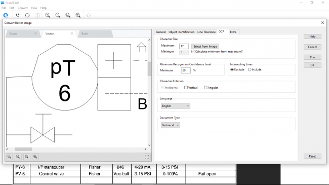
- Click the Convert raster image button. Typically, an ILD is a mechanical engineering drawing that contains lines and symbols as well as text. As such, you will first select the Mechanical preset, a vectorization preset under the General tab of the Convert Raster Image pop-up window. Secondly, choose the Vectorize and OCR options. Doing this creates an OCR tab, which you should then click and set the maximum character size. To set the maximum character size, click Select from the image and look for the text with the largest font size. You will then ‘measure’ the tallest letter’s height by dragging your mouse from the top to the letter to the bottom. This will automatically populate the Maximum field. If your ILD has angular and vertical texts, check the appropriate boxes under the Character Rotation Section. Click Run.
- Clicking Run generates a preview of the converted vector ILD, which you can then use to make minor corrections before finally exporting the final drawing. Click OK; this is the last step of converting the Instrument Loop Diagram to CAD using Scan2CAD. At this point, you may opt to export the file as is by clicking Export, which prompts you to enter the file name and choose the CAD-based file format you wish to use – you can select either DXF or DWG. Click Save.
- However, if the converted drawing contains a few errors, you may want to correct them before exporting the file. Notably, Scan2CAD has multiple tools such as erase, select (cursor), and measure and scale, as well as tools that enable you to draw lines, arcs, polygons, Bezier curves, text, circles, and rectangles. Each of these tools has a menu that allows you to draw either an outline or solid shape and check the Snap To End Points box. If you observe that the circles on the converted drawing exist as a collection of polylines and not a continuous arc, for example, you may follow the following procedure.
Example of an Error in Converting Circles
a. Overlay the raster image on top of the vector image by choosing the Both tab and clicking the Highlight vectors button. This will enable you to see the exact sections that need corrections.
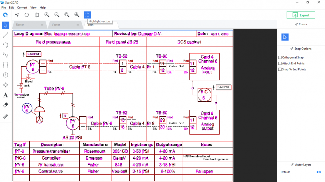
Raster on Vector Overlay
b. Use the Erase tool to delete the polylines, and then use the Draw circle button to produce a circle. Simply, you can use Scan2CAD to make all the necessary corrections, including editing text.
c. Click Export which prompts you to enter the file name and choose the CAD-based file format you wish to use – you can select either DXF or DWG.
d. Click Save to save the converted file and complete the conversion process.
6. Clicking Save results in a DXF/DWG Export Options pop-up window that you can use to make a few tweaks to the appearance of the converted Instrument Loop Diagram. For instance, by checking the Convert black vectors to white, Scan2CAD changes black lines, arcs, and text to white, thus making them visible when using a CAD program with a dark-themed background. If your CAD program has a white background, uncheck this box. Finally, click OK.
Video Tutorial: How to Convert Instrument Loop Diagrams to CAD
Parting Shot
Importantly, you may opt to make the corrections highlighted in step 5 above using a CAD software program such as AutoCAD. However, this may prove cumbersome because you will constantly have to toggle between the CAD program’s window and the reference raster ILD. This may mean that you will spend additional time making the necessary edits.
Fortunately, Scan2CAD has addressed these issues. By enabling you to overlay the raster image on top of the converted image, for instance, you have the reference file within a single window that you can then use to seamlessly make the necessary corrections. In addition, it has the essential drawing tools to facilitate the editing process. These capabilities lend credence to our earlier statement that the software is indeed versatile.
With this tutorial, we hope that you have understood what an instrument loop diagram is and how to use Scan2CAD, and the various features therein to convert Instrument Loop Diagrams (ILDs) to CAD-readable formats such as DWG and DXF.
