Table of Contents
Video Tutorial: Converting TIFF to Creo
Let’s jump straight into a video tutorial. In this video we use Scan2CAD to convert a TIFF image to DXF/DWG which can be directly imported into Creo.
An intro to Creo
Creo is a software suite developed by PTC Inc. (formerly Parametric Technology Corporation) and is the company’s flagship app line specifically crafted for the manufacturing and design industries. Originally launched from Boston, Massachusetts where PTC Inc. is headquartered, the nine-year-old app suite is internationally used and is even available in a variety of operating languages, including English, Chinese, German, Japanese, French, and Russian.
As a software suite, Creo was to designers and manufacturers at different scales of production, but individually, the apps in the suite each deliver their own set of functionalities that would cater to different niches of industry professionals. The apps are designed to work on MS Windows and can handle both 2D and 3D CAD models as well as product renderings, visualizations, and simulations.
Creo has tough competition in its industry rivals Solidworks, CATIA, and Solidedge. But potential Creo users who are familiar with those other pieces of software should have an idea of what Creo is capable of achieving.
Image quality
The main purpose of Creo as a piece of software is the drafting up of 2D orthographic plans or 3D models of a proposed product or machine part. With 3D models, users will almost always start with 2D sketches or schematics before moving on to extruding the parts in 3D and editing them up for their final touches. Users can very well create these 2D reference drawings within the software itself, but it is fairly common for users to take 2D schematics from other CAD software and import them into Creo for 3D modeling. We’ll be taking a look at the different file formats that Creo can handle later on, but in general, importing 2D schematics into Creo will have different workflows depending on whether or not we’re working with raster or vector images.
The import process of Creo has been significantly improved ever since the release of Creo 7 back in 2017. It’s as simple as choosing a few intuitive tools from the program’s toolbar, but before we dive into the details, let’s take a look at what constitutes a suitable image to import.
1. Image Clarity
With any conversion process, the biggest factor in determining the quality of the output is the quality of the source image. We need the TIFF to have clear, defined lines for conversion; any blurry areas or gradients won’t be converted well when put through the process. For images that you want to use as references for a Creo model, aim for clear, crisp lines and information.
2. Image Resolution
The resolution of an image refers to the number of pixels is has. The bigger the image, the greater the number of pixels, the better the resolution. In general, images with larger resolutions have cleaner, clearer, and crisper details than those with poor resolutions. With scanned images, we ideally want something between 300 to 500 DPI.
3. Image Colors
When using images as references for 3D models, you would want to do away with as much unnecessary information as possible. Being clear and concise is key in getting good results. So when it comes to colors, less is more. You ideally want to have something black and white, but monotone images work well too.
Importing images into Creo
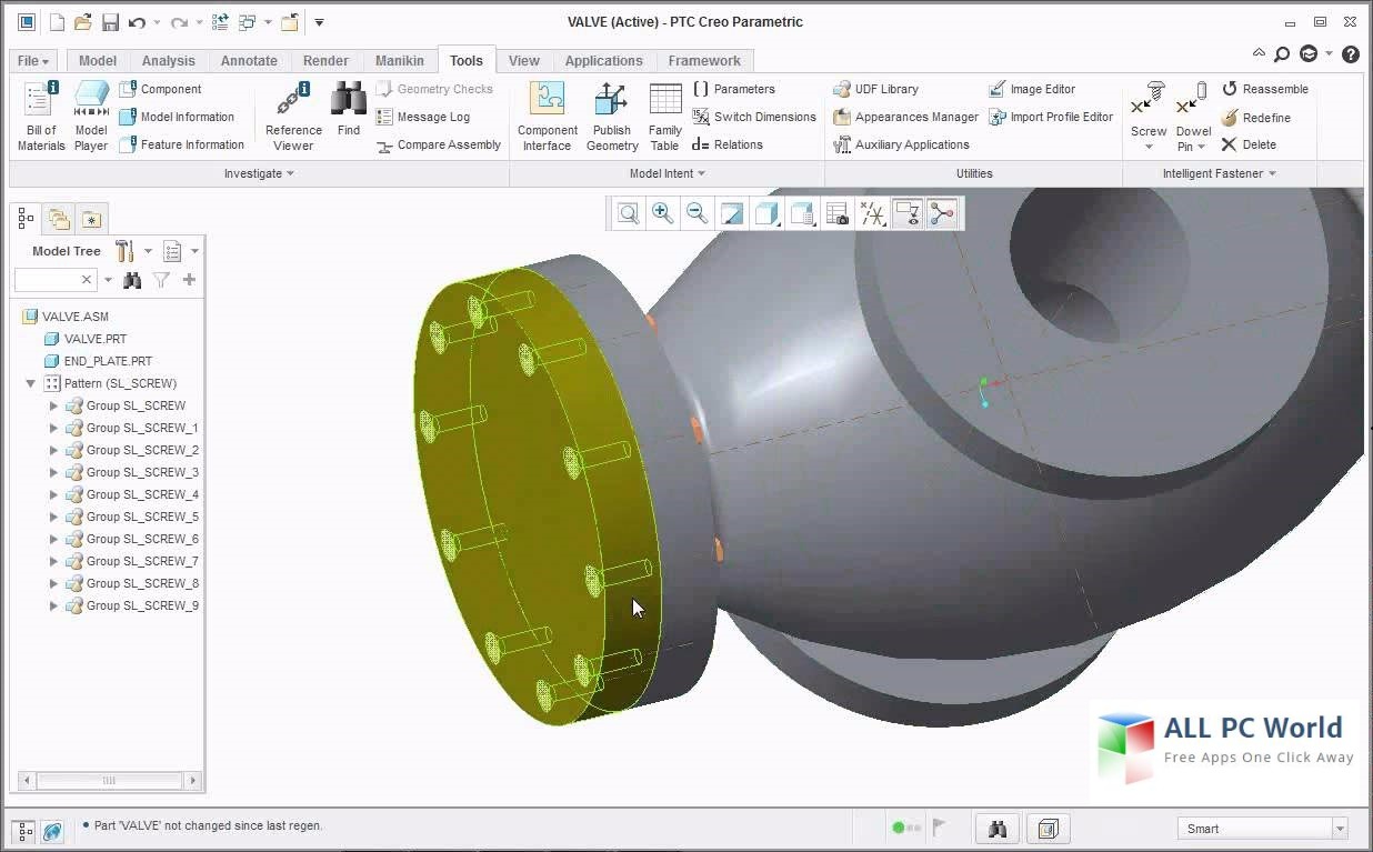
Creo’s standard user interface Source
Here’s the step-by-step process of importing a TIFF or any raster image into Creo:
- Locate the ‘Images’ button in the Layout menu and click on that.
- You’ll be seeing a dialogue box after clicking on the Images button. Browse and locate the image file you’re going to be importing. Click on ‘Open’ and the image should be inserted into your current view.
- Adjust the inserted image by dragging it to position, editing its scale, rotating it accordingly, and adjusting the transparency if you need to.
Here’s a video of the whole process for clarity:
Raster vs. Vector
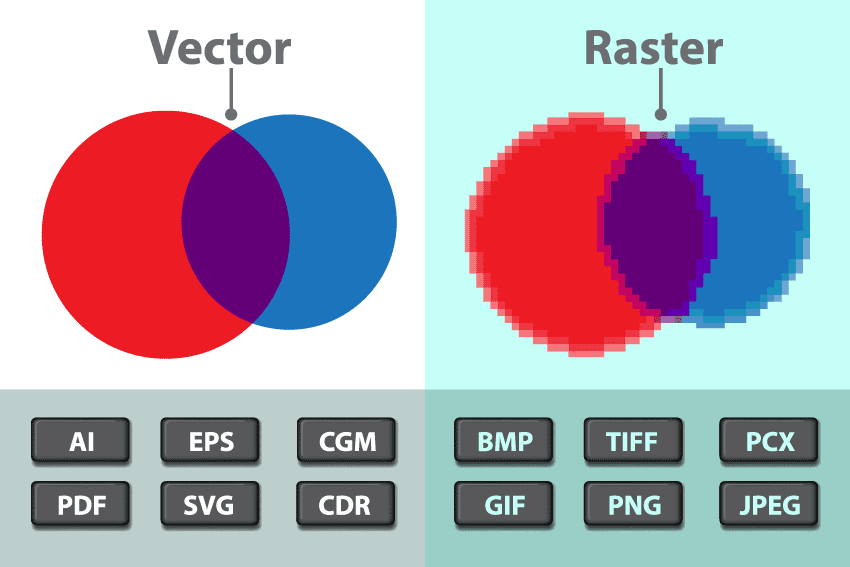
Raster and Vector Images Source
TIFF is an example of a raster type image. When importing images into Creo, you’ll find yourself dealing with basically two types of images – raster and vector.
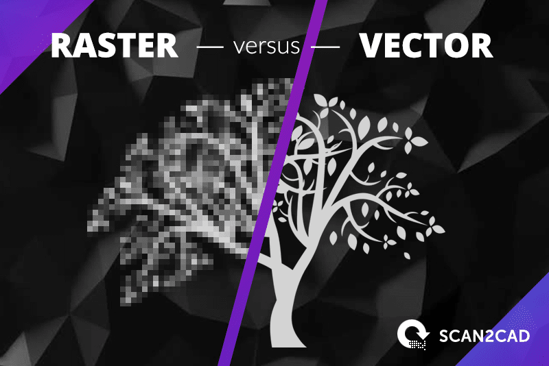
Raster images – sometimes referred to as bitmap images – are images made out of pixels. Tiny dots are clustered, arranged, and colored in a way that creates a coherent image. Other than the TIFF format, common raster formats include JPG, BMP, PNG, and GIF. For raster images, better quality files are usually those with higher resolutions.
Image files that can be directly edited and worked on in Creo are called vector files. They are made of editable geometric objects such as lines, curves, and polygons. DWG, DXF, and G-Code are common vector file formats. Vector’s main difference from raster files is its composition – customizable geometry instead of colored pixels.
In most cases, we would always prefer working with vector images when importing into Creo since vector images can’t be blurry, are readily editable, and have no need to be converted saving you time and effort. But in cases where we have to work with raster images, there are always quick ways to go about converting them into editable vector files.
Importable file formats for Creo
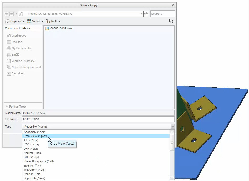
Creo supported file formats Source
Creo can import different types of file formats, both raster and vector alike. Here’s a list of all the file formats that Creo supports:
|
For Import |
|
|
3D/ 3D Model |
– Creo View (.ol) – IGES (.iges) – STEP (.stp, .step) – JT (.jt) – Stereolithography (.stl, .sla) – MicroStation (.dgn) – PTC Visualizer (.gbf, .gaf) – AutoCAD (.dxf, .dwg) |
|
2D Drawing |
– IGES (.igs) – Stamp (.png) |
|
Structure/ Compressed structure and geometry |
– Creo View (.pvs, .ed, .pvz, .edz, .zip) |
|
Parts and Assemblies |
– Creo Parametric (.prt, .asm) – VRML (.wrl, .vrml) |
|
Creo Unite |
– SolidWorks (.sldasm, .sldprt) – CATIA V5 (.cgr, .CATPart, .CATProduct) – NX (.prt) |
|
For Export |
|
|
Image files |
– Bitmap (.bmp) – GIF (.gif) – JPEG (.jpg, .jpeg) – PNG (.png) – TARGA (.tga) – TIFF (.tif, .tiff) – 2D PDF (.pdf) |
|
3D file |
– IGES (.igs) – 3D PDF (.pdf) – U3D (.u3d) – VRML (.wrl) – STEP (.stp) |
|
2D illustration file (from HLR render mode) |
– ISO (.iso) – CGM (.cgm) – SVG (.svg) |
Converting raster images for use in Creo
Some programs have automatic raster-to-vector conversion functionality but unfortunately, Creo doesn’t have that kind of tool. Lucky for us, Scan2CAD is perfectly capable of doing raster-to-vector conversions. But if you’re intent on doing everything on Creo, the best thing we can hope for is a smooth, easy manual trace conversion. This is where source image quality is such a big factor.
Sketching and drafting in Creo is pretty easy to do as long as you’re already familiar with sketching tools in other CAD programs. They come with the standard fare of sketch functions such as lines, polylines, splines, arcs, and circles. Once you’ve had time to get used to these, tracing over your reference image on Creo will be a breeze.
But regardless of your drafting skill level, manual tracing can always tend to be a little tedious. This is especially true for some of the more complicated schematic drawings. But this is where Scan2CAD comes in. Instead of taking all that time and effort and putting it into manually converting an image, you can just use Scan2CAD to automatically do the conversion for you.
How to Convert TIFF to Creo with Scan2CAD
- Take the TIFF file you want to use as a reference on Creo or whatever raster image format it is you want to convert and open it up on Scan2CAD.
- For raster images, there’s a little bit of clean-up that you’re going to have to do before the actual conversion step. Vector formats are a bit easier to deal with since you’ll really just be opening them up on Scan2CAD and then saving them in your preferred vector format. For TIFF images though, which are raster images, you’ll have to follow the next couple of steps before saving.
- The Clean image button at the top left of the interface is all we really need to press to start cleaning up the image. If it isn’t already grayed out, click on the Threshold (Black & White) option to turn the image completely monochrome. A couple of tools you can play with are Remove Speckle & Holes which gets rid of unnecessary pixels that you don’t want the program to convert, Thicken Lines which makes the thinner lines in the image just that much more legible, and Smooth to somehow soften any jagged lines you have.
- After you’re happy with the clean-up, just click on the Convert option next to Clean image. For schematic drawings, you’ll want to go with the Technical Vectorization Method. Vectorize and OCR is a useful pre-set if you have some text objects in the image you want to convert. There are more complete definitions and tutorials about all the Scan2CAD conversion settings on the website.
- Once you’re happy with the settings, click on ‘Run’ to generate a preview. If you’re happy with what you see, click on ‘OK’ to execute the process.
- With your new vector file, all that’s left is to save the file. In Creo’s case, the program can readily handle DWG or DXF files so just choose between the two.

