
Most CAD applications require users to purchase or subscribe for licenses, which is quite expensive for engineers, architectures, and designers. But that is not the case with LibreCAD, which is a free open-source CAD application for creating industrial and graphic designs. Compared to most other CAD software, LibreCAD is relatively easy to use and has a sharper learning curve. That is why Scan2CAD has prepared this simple guide to assist you to learn LibreCAD basics in just one hour.
Table of Contents
LibreCAD history
![]()
LibreCAD was started as a project for incorporating CAM capabilities into the QCad so that it would be with the Mechmate CNC router.
QCad was initially built on Qt3 library which was becoming outdated and it had to be ported to a more advanced library, the Qt4, and its name was changed to CADuntu.
After a few months, the community decided that the name CADuntu was inappropriate and they changed it to LibreCAD. The CAD application has gone on to port to Qt5 which is even more advanced than the Qt4.
- Current stable release: LibreCAD v2.2.0-rc1
- License type: GPLv2
- Operating Systems: Windows, macOS, and Linux
- Developers: the LibreCAD community
LibreCAD uses and features
LibreCAD is used for producing orthogonal and isometric projections. The orthogonal projection is for creating 2D drawings while isometric projection allows users to represent their 3D models in 2D. Isometric projections are at times referred to as 2.5D drawings.
It is also a popular DWG and DXF file format viewer and users can also use it to save drawing in DXF, and SVG, among other formats.
One of its unique features/characteristics is that it has a very highly customizable interface that allows users to customize toolbars and menus.
Orientation
For you to easily learn LibreCAD, it is important to first understand what the various parts of its interface are used for. Below is a screenshot showing the various parts of the LibreCAD interface.
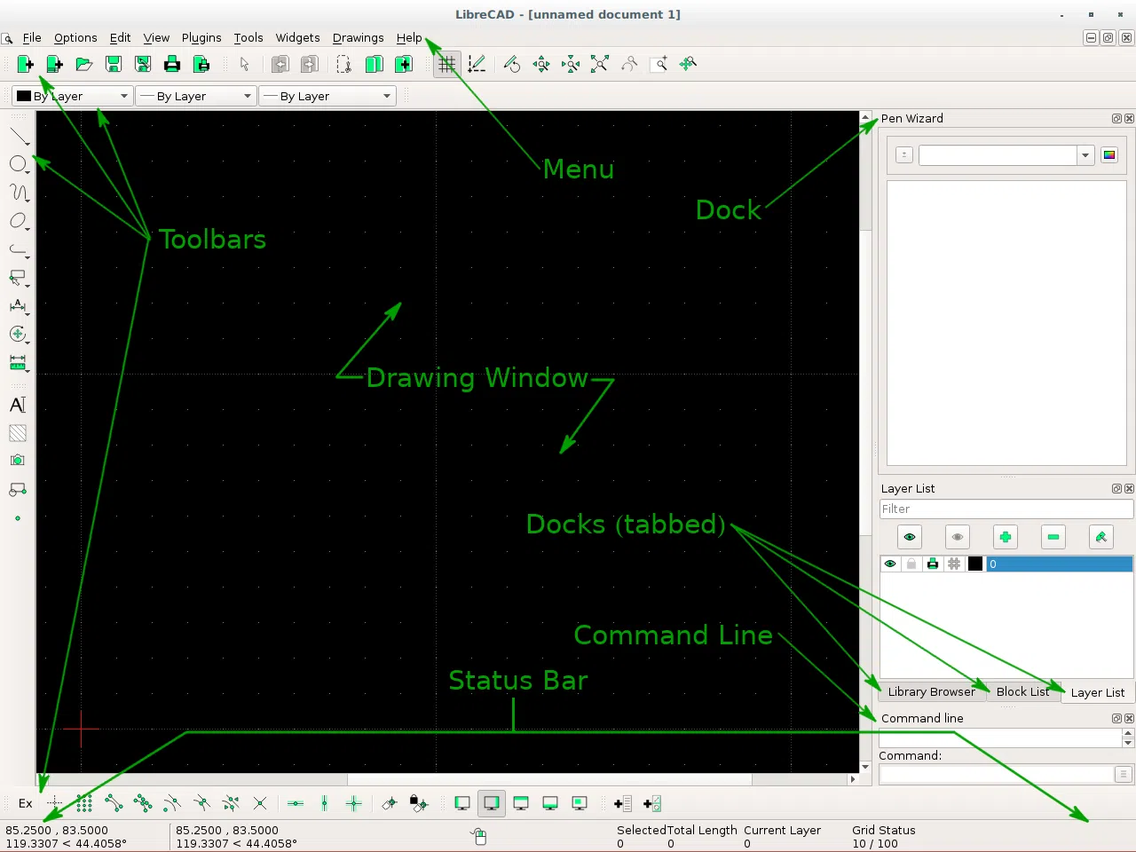
Figure 1. LibreCAD v2.2.0-rc1 Interface (Source)
From the above screenshot, it is evident that there are six main parts of the LibreCAD interface namely Menu, Toolbars, Dock areas, Drawing Window, Command-Line, and Status Bar.
The menu provides access to the main application functions found in the various menus (File, Options, Edit, View, Plugins, Tools, Widgets, Drawings, and Help)
The toolbars provide access to the various drawing tools that you may require to perform the various drawing tasks.
Docks (also commonly referred to as Dock Widgets) provide access to the most preferred/used drawing tools and functions, which are docked there.
The status bar provides you (the user) with information about the current drawing operation. It has five sections:
- Coordinates – This is where the absolute coordinates and relative coordinates of the cursor are displayed as Cartesian and polar coordinates. The absolute coordinates are displayed on the left while the relative coordinates are displayed on the right.
- Next Action – Shows a prompt of the next action.
- Selected – show the number of entities selected and the total length selected
- Current Layer – Shows the current layer in use.
- Grid – Shows the major and minor grid spacing for the X and Y axes.
The drawing window is where the active drawing (the drawing that you are working on) is displayed.

Customizing LibreCAD Interface layout
LibreCAD layout and appearance are highly customizable and you can configure it to suit your taste by creating user-defined pop-up menus, customized Dock Widgets and Toolbars, and alternative visual effects of the interface window.
To create a user-defined pop-up menu, you simply click on Options -> Widgets -> Menu Creator. Once in the Menu creator, you should select the actions from the left side that you want to include in the customized menu (shown on the left). You should also input a name for the customized menu and once complete click on Create.
You can also modify or delete an existing menu by selecting it from the Name drop-down box.
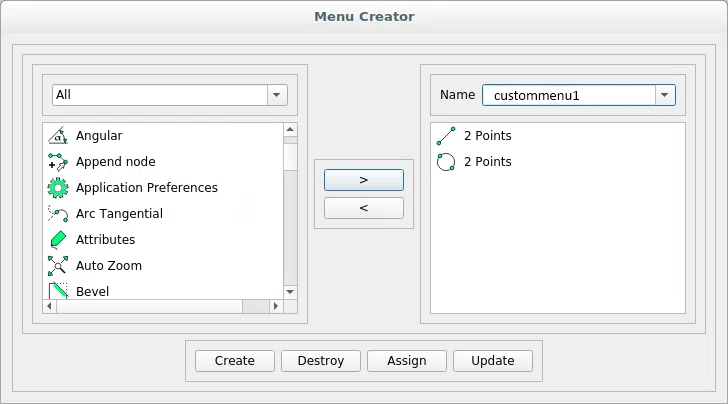
Figure 2.Creating a customized menu
You should follow the same process (Options -> Widgets) to create a custom toolbar or Widget but choose Toolbar Creator and Widget Options instead of menu creator.
Starting to Draw using LibreCAD
To start using LibreCAD, open/start the application. You may want to check the version of LibreCAD you are using to be sure if it has all the recently updated features since it is a living CAD application that is constantly being updated by the LibreCAD community.
To check the version of LibreCAD you are using, click on Help on the menu bar.
Once you are satisfied with the version you are using, you should go ahead and set your application preferences using Options -> Application Preferences -> Appearance. Here you can configure the background color to white or black or any other color that you wish to use.
Then go ahead and save the current document to ensure that your project is saved in a named document that you can easily access later. To save, go to File -> Save and input your preferred name.
Importing Freehand Sketches into LibreCAD
Most designers, architectures, and engineers start by drawing a freehand sketch of what they want to draw on a CAD application.
LibreCAD provides an option of adding freehand drawn sketches; meaning you can draw your freehand sketch, scan it as an image, and insert it into LibreCAD for use in your drawing.
To do so you should:
- Draw a neat freehand sketch (if possible without texts).
- Scan the freehand sketch as an image.
- Click on File -> Import -> Insert Image. Or click on the ‘insert image’ tool icon on the toolbar on the left
- Select the file of your scanned freehand drawing.
- Position it where you want it to be (e.g. at the top of the drawing box).
- To view the image instead of the outline, you should view it in print preview or when the draft mode is turned off.
It is however important to note that LibreCAD only accepts bitmap images and you have to ensure that your scanned image is saved as a bitmap image before trying to import it to LibreCAD.
Drawing on LibreCAD
You can opt to use the toolbars or command line to perform drawing operations in LibreCAD. The command line is used when you want your drawing to be in a very precise position within the drawing window.
When using the toolbars, you may choose to create your custom toolbar containing the tools that you feel you need or you can use the toolbar on the left and the one at the bottom by default.

Figure 3. Snap tools toolbar
The toolbar on the left contains most of the tools you will require to draw while the toolbar at the bottom of the window contains snap tools.
Figure 4. Toolbar on the left
It is important to note that the icons shown on the toolbar on the left give a hint of what the tools under that icon are for. And for you to use any of the tools from the category under any tool icon, simply click on the down arrow below the specific icon and a drop-down menu containing all the available tools in that category shall appear.
For example, if you clicked at lines, you should see the following tools:

Figure 5. Line tools
It is also possible to access the tools by clicking on the Tool menu at the top of the window and then selecting the type of tools you want. In the case of line tools, you could click on Tools -> Line. If you want to see tools for drawing circles, Tools -> Circle, and so on.
You can now draw any 2D or 2.5D shape you want using LibreCAD by choosing any of the available tools depending on the drawing operation you intend to perform.
However, for you to produce professional drawings using LibreCAD, it is important to use layers.
Using Layers in LibreCAD
The ability to use layers is one of LibreCAD’s distinguishing features.
In a nutshell, layers help to organize drawings by ensuring that entities that have common attributes or functions are put on the same layer.
For example, an architect drawing a house would have a layer for walls named “Walls” in his/her floor plan drawing. He could decide to have several other layers for things like partitions, HVAC, electrical, grid lines, etc depending on what he/she wants to include on the drawing.
The advantage of using layers is that all pen attributes of the entities in a layer can be attributed to that specific layer and they can be overridden for the entities as a whole. For example, if the architecture has a layer named “Walls”, he/she can change the line thickness of all the walls by changing it in the “layer Settings”.
How to create a layer in LibreCAD
To create a layer, simply click on the blue plus (Add layer icon) in the layer list. Specify the layer name. Then specify the color, width, and line type of the layer and click OK.
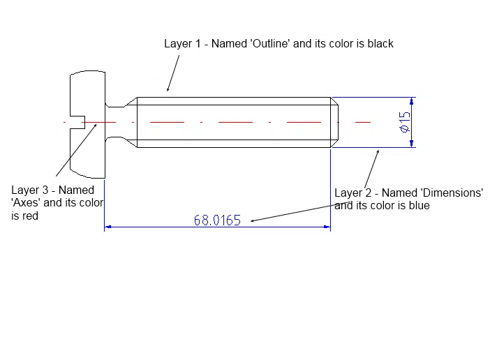
Figure 6. Drawing showing different layers in LibreCAD
When creating layers, it is important to put all the construction details or attributes that you would not want to appear in the printout in a construction layer.
To create a construction layer, simply click on the box next to ‘Construction Layer’ when creating the layer. Below is a screenshot showing how a layer is created.
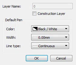
Figure 7. Creating a layer in LibreCAD
To use any of the saved layers, click on it (you will notice it appears highlighted in grey). Then once you finish using it and want the entities to be drawn using another layer. You can go back to the normal drawing layer which is designated 0 in the ‘Layer List’ or you can select another layer of your choosing.
Isometric drawing using LibreCAD
Isometric drawings allow you to represent 3D drawings in 2.5D drawings. To create an isometric drawing, you have to change the grid from a two-plane to a three-plane grid.
To do this:
- Click on edit on the top menu bar,
- Select current drawing preferences on the drop-down menu that appears,
- Select the grid tab on top in the pop-up box that appears,
- Click the isometric button in the grid options area that appears and click OK at the bottom of the area.
You should notice that there shall be more grid points since a third coordinate is added.

Figure 8. Isometric grid in LibreCAD
Conclusion
Besides being a completely free CAD software, it is also very simple to learn how to draw 2D and isometric drawings using LibreCAD.
By using this guide, you should be able to learn LibreCAD in 1 Hour.