
CNC veterans will regularly need to produce CNC files that are suitable for cutting. Most of the time, that includes taking a design and converting it into a vector file format that CNC machines can read. Taking it a step further, before even running that vector file through the machine, some CNC machinists will take the time to optimize these vectors for a smooth and high-quality end product.
All these steps might seem a little overwhelming, but Scan2CAD can execute all of them for you without a fuss. We’ll go through all of these steps in the article today, but let’s first start with a demonstration of how Scan2CAD can optimize your CNC designs for cutting.
Table of Contents
Image types for CNC cutting
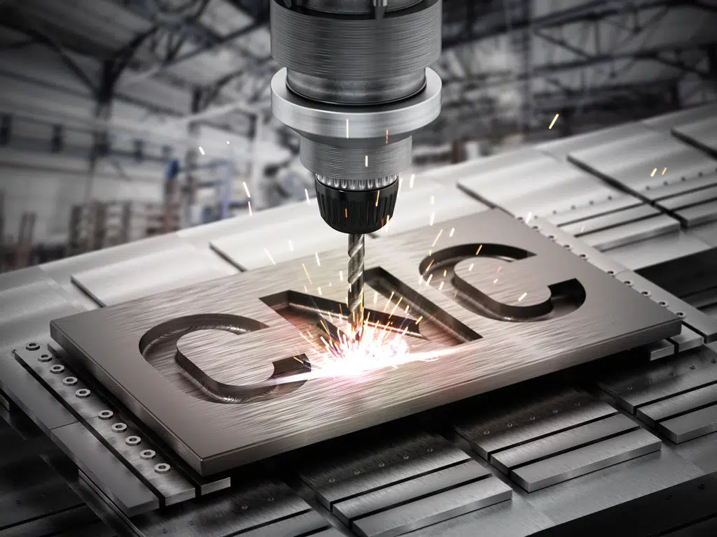
CNC machine working on steel Source
There are two things to consider before you can even start optimizing your image for CNC cutting: 1 – whether the image itself is suitable for CNC cutting and, 2 – whether the file format is suitable for CNC cutting.
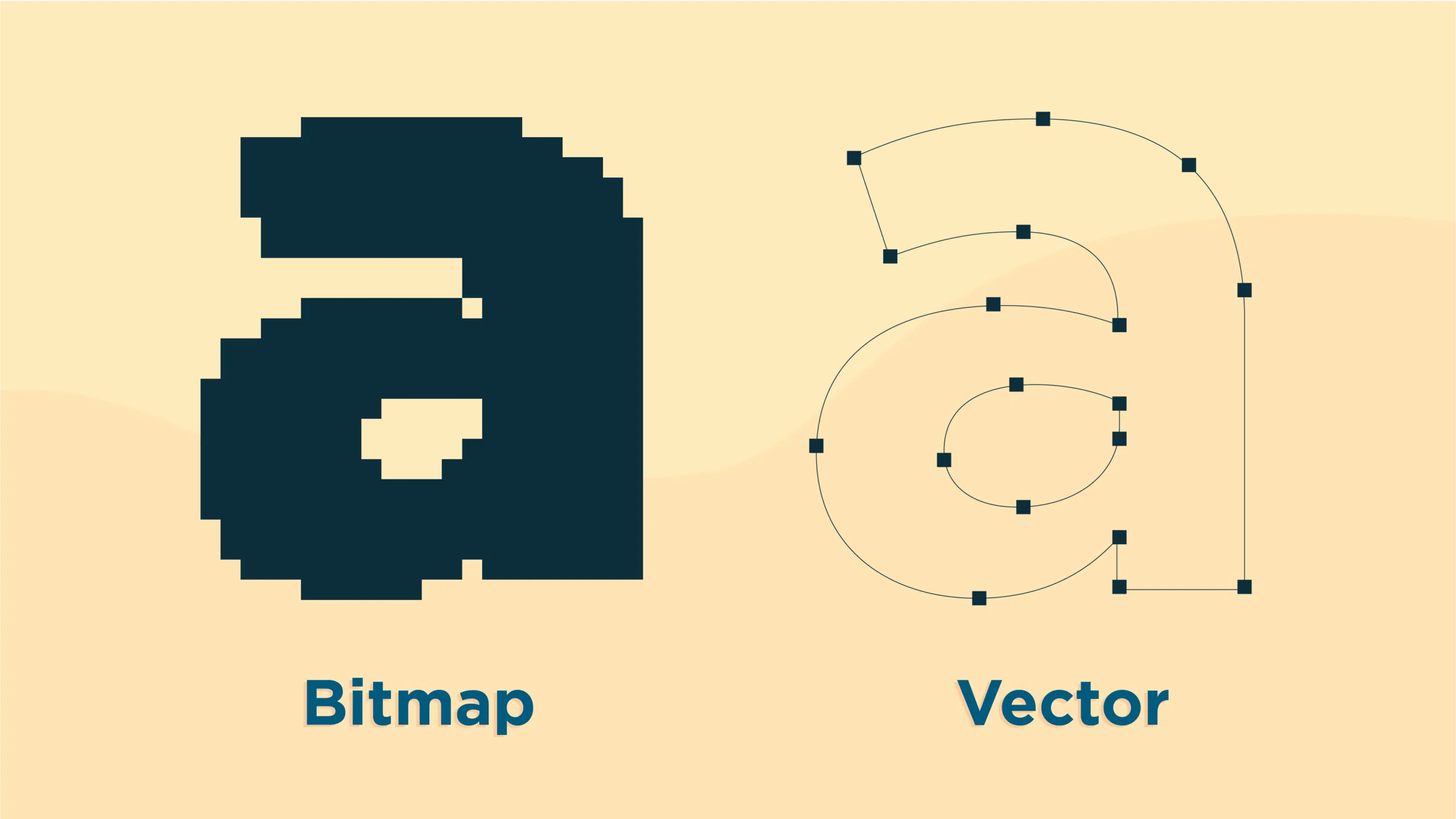
Usually, when you deal with images for CNC cutting, you want to go for monochromatic images with minimal gradients. Colored images are a bit difficult to deal with since converting them to black and white doesn’t always work out well. Anything with midtones will either be converted to black or white when setting it up for CNC cutting and so a lot of the details will get erased. Gradients are an even bigger problem for the same reason. So when you’re designing or editing an image for CNC cutting, always note that the most suitable images will be monochromatic ones that can easily be turned black and white.
When we talk about image formats, we’re looking at if the file you’re working with is a raster file or a vector file. Vector files are pretty straight-forward since the standard CNC file formats are also examples of vector files. If you’re working with a vector file – which you can tell if an image is one if it doesn’t get pixelated or blurry no matter how much you zoom in – you can go straight ahead to optimizing the file for CNC. If you’re working with raster files, however, the process is a bit more involved. You’ll have to convert that raster image into a vector file.
Conversion options

Raster to vector conversion Source
When you need to convert an image for CNC, you have three options:
- Manually trace the image using your CAD program
- Convert using built-in conversion tools in your CAD program
- Convert with conversion software like Scan2CAD
Option 1: Manual tracing
Tracing an image meant for CNC use involves opening up your raster image on your preferred CAD program and using the software’s drafting tools to vectorize all the elements of the file by “tracing” over the image. It’s the digital equivalent of duplicating a blueprint by putting tracing paper on top and copying all the lines. The process is fairly straight-forward but can get tedious and time-consuming if the image you’re working with has a complex geometry.
Some CNC users actually prefer working with manual tracing since the user will have complete control over conversion accuracy, the number of vector elements and nodes in the image, and, depending on the skill of the drafter, the ability to convert even low-resolution raster files. Do note, however, that automatic conversion tools have developed and improved to the point where their accuracy is comparable to that of manual tracing executed at a fraction of the time.
Although some conversion programs can only do so much with low-quality raster images, it can still convert such files to a point where editing and correcting any inaccuracies would still take less time than manual converting the file from scratch.
Option 2: Built-in conversion tools
Some CAD and CNC programs will have built-in conversion functionality and can automatically vectorize any imported raster images. Not all CAD programs have these tools built-in, and even those that do will have their limits. Some of the more well-known vector software that has vectorization functionality are Adobe Illustrator and Photoshop and AutoCAD’s Raster Design.
Do note, however, that these conversion tools aren’t optimized for CNC. More than likely, you’ll have to do a once-over to see if all the vectorized elements are converted properly. Still, it’s much faster than manually converting the vectors through tracing.
Option 3: Convert with conversion software
In contrast to plug-ins that only add on some functionality to a CAD program, there are other stand-alone software that specializes in raster and vector conversion. Scan2CAD is an industry leader when it comes to those types of programs and for good reason. Scan2CAD has two decades of development and experience under its belt, resulting in a conversion solution for CAD, CAM, and CNC that is precise, efficient, and easy to use.
The program handles both raster and vector conversion. That is, if you have a raster file that you want to convert into vector elements, Scan2CAD can do that for you. It can also handle vector files whose formats you want to change. The program has sophisticated object and text recognition tools to make sure that conversion go as smoothly as possible.
Additionally, Scan2CAD has a CNC optimization mode that automatically takes any existing vector file and reduces the number of nodes and poly-lines for a smoother and faster cut.
Poor conversion results
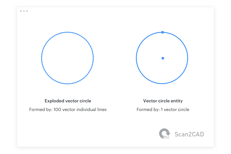
Comparing an exploded vector circle with a circle entity Source
How do qualify the type of results that we get from vector converters? A good metric would be to see if the program converts obvious arcs or circles into several small line segments. If the software can’t reliably produce arcs or circles, it might not be the best program to produce designs for CNC cutting. Smaller polylines aren’t ideal for CNC cutting because it makes the file unnecessarily complex with the sheer number of vector objects in the image. Not to mention, the CNC machine will sometimes create jagged arcs when you scale the design up.
In this type of conversion where all elements, regardless of the apparent curve, are converted into individual connected vector lines, optimization becomes a bit of a task. Not only do you have to manually erase the polylines, but you’ll also have to redraw these as arcs. Fortunately, Scan2CAD’s sophisticated object recognition as well as vector optimization tools solve all of these problems.
Object recognition simply means that if the raster image has graphics that are meant to show curves or circles, Scan2CAD will recognize this and also vectorize these elements as arcs or circles. Additionally, if you want to optimize your vector files even more, Scan2CAD can also process the image to minimize the number of vector objects and smoothen out any jagged polyline edges.
Raster text
When it comes to raster text, you’d usually want to go with conversion software that has good OCR capabilities. When it comes to CNC, however, things are a little bit different. CNC machines don’t normally handle vector text objects well, so your best bet is to convert any raster text into vector lines and arcs.
Scan2CAD has a reliable OCR conversion tool that lets you convert raster text into editable vector text. However, as in the case with CNC files, if you’d rather convert the raster text into vector lines, all you have to do is opt to go without OCR and Scan2CAD will turn that raster text into exploded lines and arcs.
Raster text and exploded vector text Source

Optimizing a design for CNC using Scan2CAD
When you have your vector file converted and ready to be used for CNC cutting, the last step would be to make sure that the file is optimized for the process. You can opt to do that manually by going through the image and smoothing out any jagged edges yourself, but automatic optimization solutions like Scan2CAD has are much more efficient.
Here are the steps for optimizing your design for CNC cutting using Scan2CAD:
- With your vector file opened up on Scan2CAD, right-click on the Vector tab header and choose File Statistics. This opens up a window where you can see the actual number of vector objects in the file.
- To optimize the vector, just click on the ‘Convert vector image’ tool at the top of the Scan2CAD interface. A dialog box should open up.
- Under ‘Conversion options’, be sure to tick ‘CNC Smoothing’.
- In the now available ‘CNC Smoothing’ tab, edit the settings as you see fit. If you’re not sure about what edits to make, the default settings are usually good enough left as they are.
- Click on ‘Run’ once you’re okay with the settings to generate a preview at the left side of the dialog box. You can click on the ‘Highlight vectors’ tool at the bottom-right corner of the preview window to have a more detailed look at the vector objects in the image. Red highlights mean the vectors are lines, pink highlights indicate arcs, and blue highlighted vectors are circles.
- If you’re happy with the preview and want to finalize the optimization, click on ‘OK’ to execute the changes. Once you’re back in the main screen, you can go ahead and click on the ‘Export’ option at the top-right of the interface and save your file under the file name and file format of your choice.
With Scan2CAD, the conversion and optimization processes are as easy and as efficient as they can be. Most images won’t take even 5 minutes to get ready for CNC cutting. If you’re a frequent user of CNC software and want to save time and money with the whole process, Scan2CAD is absolutely a must-have.
