
CNC technology has revolutionized the design and manufacturing industries. Although it’s been available for a while now – the first CNC milling machine was developed in the early 1950s – only recently has it gained traction outside of industrial and commercial setups. For the first time since its conception, CNC machines have been made widely available to the manufacturing public, becoming more accessible to weekend DIY crafters and small to mid-scale businesses and professionals. And that, in turn, has more people interested not just in using their own CNC machines, but even in outsourcing any CNC designs they might want to be cut out using industrial-grade machines.

The typical CNC process Source
The allure of a computer doing the heavy-lifting when it comes to milling complex parts is enticing. But before diving into the world of CNC, designers have to first understand how to make the most of the machines. Hardware is one thing, but the factor that all CNC users will have complete control over is the quality of the designed parts for CNC cutting.
We’ll be taking a look at some quick tips and guidelines that you can follow to make sure that your design is optimized for CNC cutting. With these and proper research, you’ll be able to make the most out of CNC machines and automatic milling processes to maximize efficiency and ease-of-use.
Table of Contents
Tip 1: Understand Your CNC’s limitations

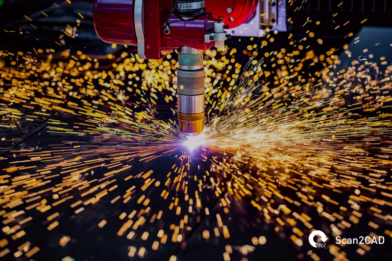
CNC machines and their limits Source
CNC cutting is a robust process; it’s flexible and versatile enough to handle almost anything that you throw at it. But like with any process, it has its limitations. Not to mention that most personal-use commercial-grade CNC machines also don’t have the capabilities of factory-grade ones. So it’s important to understand what your machine can and can’t do to be able to use it effectively.
Firstly, consider the geometry and dimensions of your CNC tool. Most CNC machines will have cylindrical drills with a set cutting length. When using the CNC to mill out parts from your materials, you can’t disregard the effects of those tool geometries on the finished product. That is, expect your internal cut-out corners to have a radius that is equal to or larger than the radius of the CNC’s drill bit, and don’t expect the CNC machine to cut through any material thicker than its working cutting length.
Another important limitation to consider is the working range of your CNC mill. Most commercially-available CNC machines will be cutting from right above the plane of your chosen workpiece. You won’t be able to use the CNC machine to cut out parts that are on a vastly different angle, i.e. from the side. As such, it gets a bit more tricky to machine out any designs that are as wide as they are long.
Of course, this particular limitation can be somewhat mitigated by more higher-end machines. If you want to go all out, you can go ahead and get state-of-the-art 5-Axis CNC machines. But if you’re not ready to dish out that kind of money, just stick to making sure your design takes into consideration your chosen CNC machine’s limitations.
Tip 2: Design each part with the CNC in mind

CNC-machined parts Source
When designing the parts to be milled, it’s important to not just look at the designs in their entirety but to also pay close attention to the individual parts that make up the design. Keeping your CNC’s capabilities in mind will help you figure out what parts of your design might be unfeasible and require design edits.
In particular, pay attention to these parts of your design:
- Holes and cavities – Make sure you set the radius of any pockets in your design to be at least three times the diameter of your CNC’s cutting tool to prevent going beyond the machine’s recommended cutting length.
- Internal corners and edges – As mentioned in the CNC limits section, make sure to give ample allowance for any internal corners taking into consideration the diameter of your drill bit.
- Wall thickness – When designing your part, make sure that any walls are thick enough that there aren’t any substantial vibrations during the milling process. Thin walls make for excessive vibrations and that leads to inaccuracies in the resulting product. In general, metal can handle vibrations better than plastic so you should leave a bit more leeway when it comes to plastic materials.
Tip 3: Machine tolerance

CNC tolerance Source
When talking about a CNC machine’s tolerance, this refers to the amount of error or variation that is acceptable when milling out parts from materials. There are two types of CNC tolerances: general tolerance and part tolerance.
The first – general tolerance – refers to the overall machine tolerance for the designed parts in their entirety. This is usually plus or minus five-thousandths of an inch for metals and a hundredth of an inch for plastics. Different CNC companies have varying degrees of general tolerances that they use when clients don’t specify their own general tolerance.
Part tolerances refer to any element of the design that has to be more accurate than most of the other parts of the CNC design. More accurate designs usually mean a more meticulous prep time and a more involved CNC milling process. As such, more specific part tolerances will most likely result in longer processing times and, for any outsourced CNC work, heftier service fees.
Keeping machine tolerances in mind is useful when designing machine parts that need a high degree of precision.
Tip 4: Keep within size limitations

A medium-sized CNC Source
The overall size of your design is a big factor to consider when it comes to CNC. Needless to say, having design parts that are too big to fit into the machines you are planning to use is a no-go and will usually require you to break them down into smaller designed pieces that would fit together. But it’s also important to understand that you also can’t go too small with parts or the machines won’t be able to handle that amount of precision detailing.
It’s also useful to keep in mind the size of the materials you’re planning to use. You can’t, for example, plan to CNC machine a part that’s longer than the longest dimension of the metal or plastic material you’re planning to use. Which brings us to the next tip…
Tip 5: Consider your materials

CNC-machined materials Source
Choosing a material is a big factor when it comes to optimizing your CNC design. You have to consider characteristics such as weight, rigidity, thermal and chemical resistance, and density. Other things to consider are ease-of-use and cost.
In general, you’ll be working with three types of materials suitable for CNC machining – metals, plastics, and wood.
Metals are the industry standard for factory-grade industrially CNC-machined parts. Softer materials such as aluminum are favored but if metals with denser and heavier characteristics are made, steel is usually used.
Plastics are much more cost-effective than metals but do not nearly have the rigidity, weight, and structural integrity that metals do. In this manner, they are useful for parts that do not encounter too much stress or extreme wear and tear.
Wood materials are almost exclusively used for furniture or finishing fixtures. Out of the three, this is the most cost-effective and easiest to work with, but has its niche in the construction and furniture manufacturing industries.
Tip 6: General last-minute considerations
Lastly, you can easily check off the following with your CNC vector file before sending it off to the machine:
– Make sure the vector has single-line paths and that each line connects to the endpoint of the next line. Sometimes, it’s easy to overlook any endpoints that are close together but not actually touching. Check corners and curves.
– Try to minimize nodes and intersections when you can. Without compromising the quality of the design, less is more when it comes to CNC.
– Prioritize polylines over arcs or beziers as most CNC machines prefer to work with polylines.
Luckily, Scan2CAD has streamlined vector optimization with the following steps:
- With your vector file opened on Scan2CAD, click on the Convert > Convert Vector Image.
- In the dialog box that pops up, click on the ‘CNC Smoothing’ option under ‘Conversion options’.
- The default settings of this options should be fine, but feel free to double-check by clicking on the ‘CNC Smoothing’ tab at the top of the dialog box. Here you’ll see the different settings for Lines, Arcs, and Beziers.
- Click on Run to generate a preview using your settings and then click on OK to execute the optimizations once you find the preview to be acceptable.
- Click on Export at the top-right of the interface. Name your optimized file and choose a file format from the options available.
Conclusion
In short, it pays to know all the particulars about the CNC machining process so you can plan your designs accordingly. Make sure you know your CNC machine or the company that you’re planning to outsource to, the material you’re planning to use, and the tolerances of the final product when compared to its intended use.
Although it might seem a little bit intimidating, keep in mind that designing your machined parts is a whole process. As long as you keep these tips and guidelines in mind when drafting out every individual element, you should be golden.
