
Some CNC machines cannot use splines for accurate machining—especially lower-end CNC programs, as well as plasma, laser and waterjet cutters. It’s a nuisance when you export your CAD design onto the software and realize that all the splines in your design cannot be recognised by your CNC software! When you find yourself in this inconvenient situation, you have two options. You could trace your splines manually using lines and arcs (both of these are simpler CAD entities), or make use of Scan2CAD’s automatic vector editing tool to save yourself some time. Learn more about this nifty trick in our guide below.
Compared: Splines vs. polylines

Splines vs. polylines. Image source: knowledge.autodesk.com
Polyline
Polylines are entities that are made up of lots of shorter lines and arcs that have been joined into one.
In Scan2CAD, you can create a polyline from consecutive lines and arcs by selecting Vector Edit Menu > Modify > Make Polylines.
Spline
A spline is a smooth curve that passes through two or more specific points. The term has its roots from the good old days of mechanical drafting. Back then, a flexible metal or wooden strip (called a spline) was used to construct mathematical graphs. In the world of computer graphics today, splines are easily edited by moving control points; you can add, remove or move control points to alter the size and shape of the spline.
Another term that you might come across often in CAD is Bezier curve. A Bezier curve is a special type of spline, which is defined by only one polynomial function. In layman’s terms, a Bezier curve is defined by only four points (two end points and two control points). Meanwhile, a spline is a more general term; a spline can comprise of multiple Bezier curves linked together.
Why convert splines to polylines?
While CNC incompatibility is the most popular reason for converting splines to polylines, there are some users who do so to get a more optimized design. In the image below, the curvefitted polyline is 38% more compact than the original spline! The original spline had 70 control points, which was later converted to just 43 arcs and lines. The resulting drawing matches very closely too!
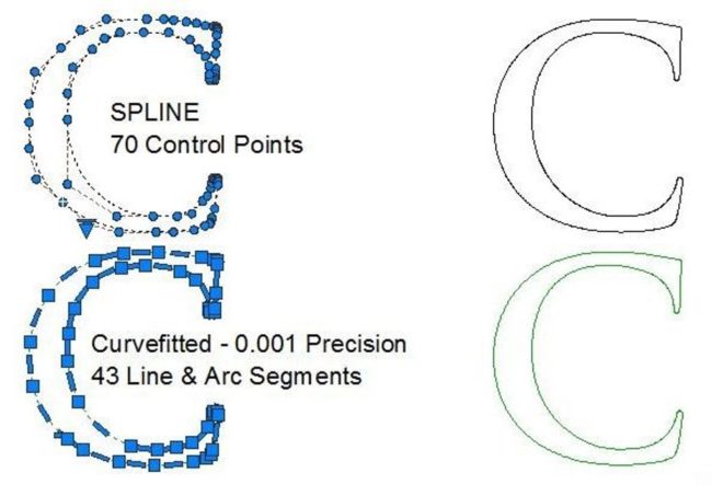
The letter ‘C’ on the top is a spline, whereas the bottom image is a polyline. In this case, the polyline is more compact than the spline. Image source: TCICorp.com
Finally, there are some vector editing actions that you just can’t do to a spline (e.g. changing the width). Of course, these features depend on the CAD software you’re working with. Therefore, some people find it easier to work with polylines, as these are simpler vector entities that are supported by all CAD programs.
Step-by-step guide using Scan2CAD
- Select Vector Edit Menu > Modify > Bezier to Line
- Select the spline that you’d like to convert with your mouse.
- That’s it!
Tip on selecting vectors in Scan2CAD: A little box will appear on your graphic cursor; this indicates whether your vector is within Grab Snap Distance. Make sure that the vector you want to edit falls inside this box, then click!)
Using AutoCAD? Here is a guide on how to convert splines to polylines using AutoCAD.
Handy Tips for Conversion

You can compare any vectors after editing using Scan2CAD’s View Vector Ghosts function. The original Bezier curve is shown as a pale gray “ghost”. This “ghost” disappears when you change the zoom levels or pan across the screen. Turn this cool function on by hitting Shift+G on your keyboard.
The lower the precision, the larger the variation between the original spline and the new shape constructed from polylines. If you select a low precision/large tolerance value, the original spline profile will be made up of fewer and longer line segments. Conversely, a high precision value results in many short line segments.
- If you’re using your design in a CNC application, don’t convert your splines using too high precision. The CNC machine will have a very hard time tracing many short segments. The machine will jerk a lot and you’ll end up with a very ragged edge.
- On the flip side, you will want to retain your free-form curve shape to a reasonable degree of accuracy and not lose any intended smoothness.
- Consider the type of design that you’re working with. If you’re producing an object that will get heavily sanded into shape, you have more room to work with and can use lower precision when converting splines into polylines.
For more handy tips, follow Scan2CAD’s Tips and Tricks for Users blog. If you have a question we haven’t answered, feel free to ask a CAD Expert over at our CAD Answers forum.
