CAD is a crucial aspect of manufacturing and product development. Thankfully, solutions that enable you to design highly accurate models are readily available. In most cases, design has to be carried out before you even consider manufacturing. One of the most popular manufacturing processes available is CNC machining. Considering this, it is not enough for mechanical CAD software to be capable of producing superb models. CAD software for mechanical designs need to have features that enable designers to create with CNC in mind. This will maximize the speed and efficiency of manufacturing, and significantly reduce errors, as possible hiccups can be identified and eliminated early in the design stage.
In this article, we will be going through five of the best CNC design software. We will go through their features, capabilities, and any other reasons why they are considered the business. Read to the end for some bonus design tips.
Table of Contents
SolidWorks CAM
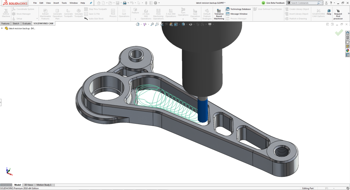
SolidWorks CAM interface (Source)
The first software package on our list is from Dassault systems – makers of SolidWorks and other powerful CAD packages. SolidWorks CAM is a separately sold add-on for all versions of SolidWorks. It enables you to ready your design for manufacturing, at the early stages of the product development process. It delivers fully integrated, knowledge-based CNC programming, right inside the SolidWorks interface. This software generates machining information fast, using automatic feature recognition, standard operations, and strategies with your own best practices.
Factors like cut depth, tool type, and tool size instantly appear to the model. This frees up your time to focus on more critical areas of design. At any time, additional machining operations can be manually created using the SolidWorks model geometry. Surfaces to machine, as well as areas to avoid, can be defined using a comprehensive suite of selection options. This eliminates the need to create additional reference geometry on the part.
Using SolidWorks CAM simulation capabilities, cutting tool paths can be produced and compared against the original model, helping you to identify any potential problems or areas that require further adjustments, long before the physical part is machined. Any changes made to the SolidWorks design can be instantly applied to your machining operations and cutting tool parts, making it quick and easy to evaluate parts for manufacture, early in development.
There are four different SolidWorks CAM packages with varying levels of functionality. These packages are sold separately. They are as follows; SolidWorks CAM standard, SolidWorks CAM professional, SolidWorks CAM machinist standard, and SolidWorks CAM machinist professional.
AutoCAD mechanical
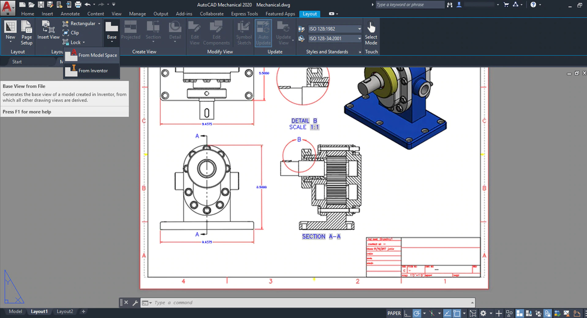
AutoCAD mechanical interface (Source)
AutoCAD is usually a part of any list that is related to CAD compatibility. Our list of best CNC design software is no exception. Previously, several industry-specific AutoCAD products were available. One of these is AutoCAD mechanical. However, in 2019, AutoCAD mechanical, along with other products were united as toolsets under a single software package.
AutoCAD mechanical is an AutoCAD toolset dedicated to DFM (Design For Manufacture). Its features allow you to create, modify and document mechanical designs for manufacturing processes, notably CNC machining. You can also dimension, create bills of materials, and generate machine components. This package comes with a parts and symbols library of over 700,000 mechanical components, which significantly reduce your design efforts. Some features of AutoCAD mechanical that directly favor CNC machining are as follows.
Machining generators and calculators. These allow you to analyze designs efficiently and include belt, chain, cam, shaft, and spring generators.
Support for international drafting standards that enable you to deliver standard, machine-compatible design documentation.
Associative balloons and bills of materials for creating automated part lists and bills of materials that increase the productivity of the CNC machining process.
Command preview and contextual menus that allow you to preview fillets and chamfers for their machinability.
Create and save custom content for machining repeatability.
Use intelligent drawing tools made for mechanical design.
Inventor CAM
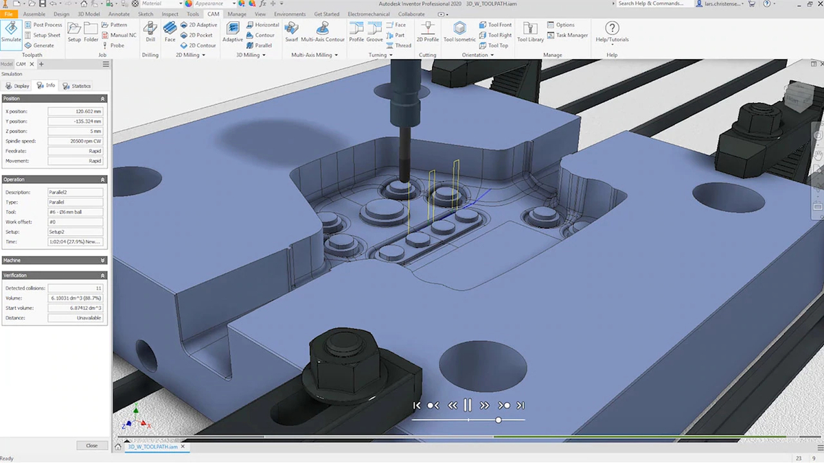
Inventor CAM interface (Source)
Inventor CAM is an add-on to Autodesk inventor that serves as an integrated CAM software to simplify CNC design and programming. This software makes the machining workflow easier with CAD embedded 2-axis and 5-axis turning, milling, and mill-turn capabilities.
Inventor CAM has a lot of features for CNC machining design. Some of these features are as follows.
Adaptive clearing. You can greatly reduce roughing time by a factor of at least four, compared to traditional roughing. Thereby increasing tool life.
2.5-axis and 3-axis milling. Using a complete package for minimizing tool paths in the industry, you can create and simulate tool paths for your model, right in the inventor interface.
4-axis and 5-axis milling. Use simultaneous 4 and 5-axis features to machine complex models such as tilt, swarf, and contours.
Turning and mill-turn. You can enhance productivity with traditional facing, boring, turning, and grooving functions. Included support for live tooling multi-turning.
Water jet, plasma cutting, and laser cutting. Quickly create 2D profile cutting paths with the ability to include all contours in the same planes, add tabs, and specify quality settings.
Probing. Automatically prevent collisions between tool holders and your part during CNC calculations.
Slope machining. Control cutter engagement to minimize tool deflection and improve finish by using slope angles.
Stock and tool path simulation. Simulate the removal of the stock in order to check for collisions between clamp/fixture and shaft.
Analysis tools to measure distances or to dynamically view crucial information such as feed, speed, and estimated machining time.
The excellent CAD features of Inventor, combined with the highly advanced CAM features of Inventor CAM, make these software packages great for designing for CNC machining.
Note, however, that Inventor CAM cannot be purchased independently and can only be acquired as part of Autodesk product design and manufacturing collection.
Fusion 360
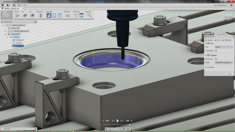
Fusion 360 interface (Source)
Fusion 360 is a fully integrated CAD, CAM, and CAE software that unifies design, manufacturing, and engineering into one platform. It is a complete package for anything design and manufacturing.
This package has a portfolio of highly advanced features for 3D design and modeling, simulation, generative design, data management, and collaboration. Combined with its manufacturing features, these make Fusion 360 one of the best CAD software for CNC machining.
Fusion 360 CAM features can be classified under the following headings.
2.5 and 3-axis milling. This allows you to quickly set up jobs and generate tool paths to machine quality parts while reducing the wear on your tools.
3+2 milling (5-axis positional). Significantly reduce machine set up time between operations by using straight forward 5-axis programming.
4-axis milling. Create wrapped or indexed tool paths with the rotary axis of your machine to create complex geometry.
5-axis simultaneous milling. Use simultaneous full 5-axis operations to avoid collisions, mill complex geometry, and reduce till lengths for high-quality surface finish
Set up probing. Exploit machine touch proves to make your setup process easier.
Turning. Use stock simulation to verify your turning tool paths in order to identify errors and prevent collisions with the model, tools, work holder, and stock.
Mill-turning. This allows you to combine milling and turning operations to create highly complex parts without having to switch machines.
Water jet, laser cutter, plasma cutter. Generate tool paths based on solid model features such as flattened sheet metal components to operate water jet, plasma, and laser cutters.
In addition to all these, Fusion 360 includes a free, open-source, fully editable, post-processor library.
Solid Edge
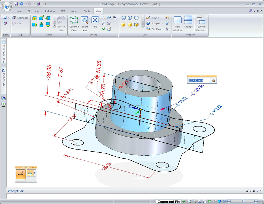
Solid Edge interface (Source)
Solid Edge is a 2D drafting, 3D solid modeling, and manufacturing CAD/CAM software for all things product development. Using synchronous technology, Solid Edge combines the speed and simplicity of direct modeling with the flexibility and control of parametric modeling. This package boasts of a complete portfolio of tools required for not only mechanical and electrical designs but also manufacturing.
The design features of Solid Edge, which include reverse engineering, convergent modeling, and generative design, are all applicable with CNC machining in mind. Solid Edge simulation capabilities allow you to fully analyze 3D parts and assemblies. You can also manage data, author technical publications, and collaborate on the cloud.
Solid Edge provides advanced tools required to manufacture complex products using either CNC machining or 3D printing. Machine tool programming that caters to all types of numerical control manufacturing processes, from basic CNC programming to high-speed and multi-axis milling is available in Solid Edge.
Three ways to improve your CAD designs for CNC machining
Avoid designing features that cannot be CNC machined
Not all the features of a part can be produced through CNC machining. Curved holes are an example of an impossible to machine features as the cutting tools in CNC mills, lathes, and drills are straight and cannot create curved holes. Such features should be avoided when modeling for CNC machining. However, if these features are a necessity for your part, you may electrical discharge machining (EDM).
Always design internal angles with radii
CNC milling tools are cylindrical. Because of this, cutting tools usually create radii when milling internal vertical edges. It is therefore recommended when designing for CNC machining to design curved angles for internal edges. Considering that the milling tool will inevitably create a radius automatically, it is best to include it in your design in the first place.
If your part, such as cavities in which a rectangular-shaped part needs to fit, requires sharp-edged internal angles, it is best to design the cavity with undercuts.
Avoid excessive use of tolerances
Tolerances are very important for machining accuracy. However, designers should only use them on necessary features such as mating parts, as excessive tolerancing would only increase machining time and cost. CNC machines differ tolerance standards and accuracy. Therefore if your dimensions have no tolerancing, the machine would use its standard tolerance for such dimensions. To save time and cost, tight tolerances should only be specified when necessary. It is also crucial to maintain uniform tolerancing as this would reduce machining time.


