
There has been increasing interest in CNC machining the past couple of years. It’s become easier than ever to get a digital copy of patterns you want to cut out and get a machine to do all the hard work for you. Most Scan2CAD users who have experience using CNC machines are also avid woodworkers and creators with a whole bunch of different tools they use in the workshop. And a lot of these users have utilized shadow boards to help organize and store their tools.
For those of us who have never encountered the term before, shadow boards are devices that indicate where tools should be placed when not in use. Mainly used for organization, shadow boards have outlines of a workshop’s tools place on them to make it easy for collaborating manufacturers to know which of their tools are currently in use or are missing. Shadow boards are useful in that they minimize both the time spent looking for tools as well as the probability of losing these tools.
Aside from manually tracing around tools to create shadow boards, Scan2CAD has made it possible to get photographs or these tools and convert these raster images into vector images. These vector images can then be used to cut out the tool shapes in wood or foam or to simply print them out onto shadow boards directly.
In this post, we’ll take a look at the steps involved in converting tools to vector outlines for use in shadow boards.
Table of Contents
Video Tutorial: Converting a tool to vector
For those of you who might want a more thorough step-by-step demonstration of this process, we have a video that should guide you through the conversion:
quality of the source image
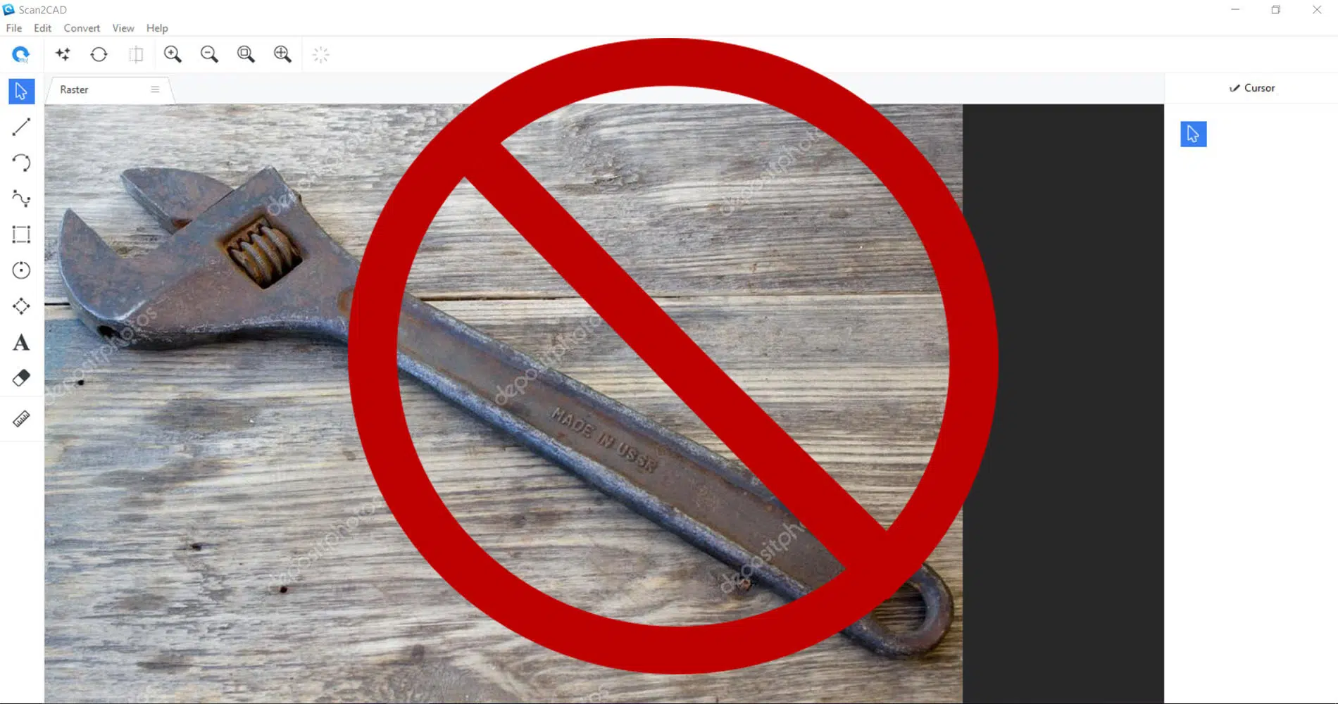
An example of an unsuitable image
Photographs are, at first glance, the quickest way to take raster images of your tools to use on Scan2CAD. However, there are a couple of key considerations we have to take note of before taking photos.
Distortion
As photographs capture images in perspective, there will always be some amount of distortion when taking them. This isn’t ideal if we’re looking to make digital outlines for use in shadow boards.
To reduce this, photography-savvy users can find the right camera lens to use to minimize distortion. You can also correct this using post-editing techniques on your preferred photo editing software.
Alternatively, you can opt to also take photos of your tools one tool at a time. Be sure to angle the camera right on top of the tool, as close to perfectly parallel as you can get.
Shadows
Shadows are also going to be an issue when taking photos for Scan2CAD. The way the software works is that it takes the outlines of the tools and converts those into vector lines. If there are shadows behind the tools in the photo, Scan2CAD will take those shadows as part of the tools and include them in the outline as well.
We can mitigate this by using lightboxes or by taking the photos in well-lit areas, maybe even outside in the sun.
Background contrast
Scan2CAD will have a hard time figuring out the outlines of tools if the tools have the same color as the background they’re photographed on.
Be sure to pick a background that has a high value contrast to the tools you’re photographing. So if you’re taking a picture of a dark-colored tool, do it against a white background. If it’s a light-colored tool, find a dark background.
Quality
And something that might be common sense to most users but we would be remiss in not mentioning – make sure your photographs are high resolution.
With any conversion software, the output is dependent on the quality of the input. Make sure your photo has a high DPI (we recommend 300-600).

A suitable image for conversion
If you’re not too keen on taking photos of your tools with all of these considerations, there are other ways to do all this with a scanner. The advantage of using a scanner is you don’t have to worry about most of these problems on distortion and shadows – the scanner makes sure all scanned images are perfectly parallel and viewable.

If your tools can sit on the scanner bed, that would be ideal. If it’s just a bit too bulky or you don’t want to risk busting your scanner, you can always manually trace your tool onto a piece of paper and then proceed to scan that.
You can check out our guide (https://www.scan2cad.com/articles/scanning-a-drawing-for-optimal-raster-to-vector-conversion-results/) to scanner settings for more information.
Cleaning up the image
Cleaning up the raster image
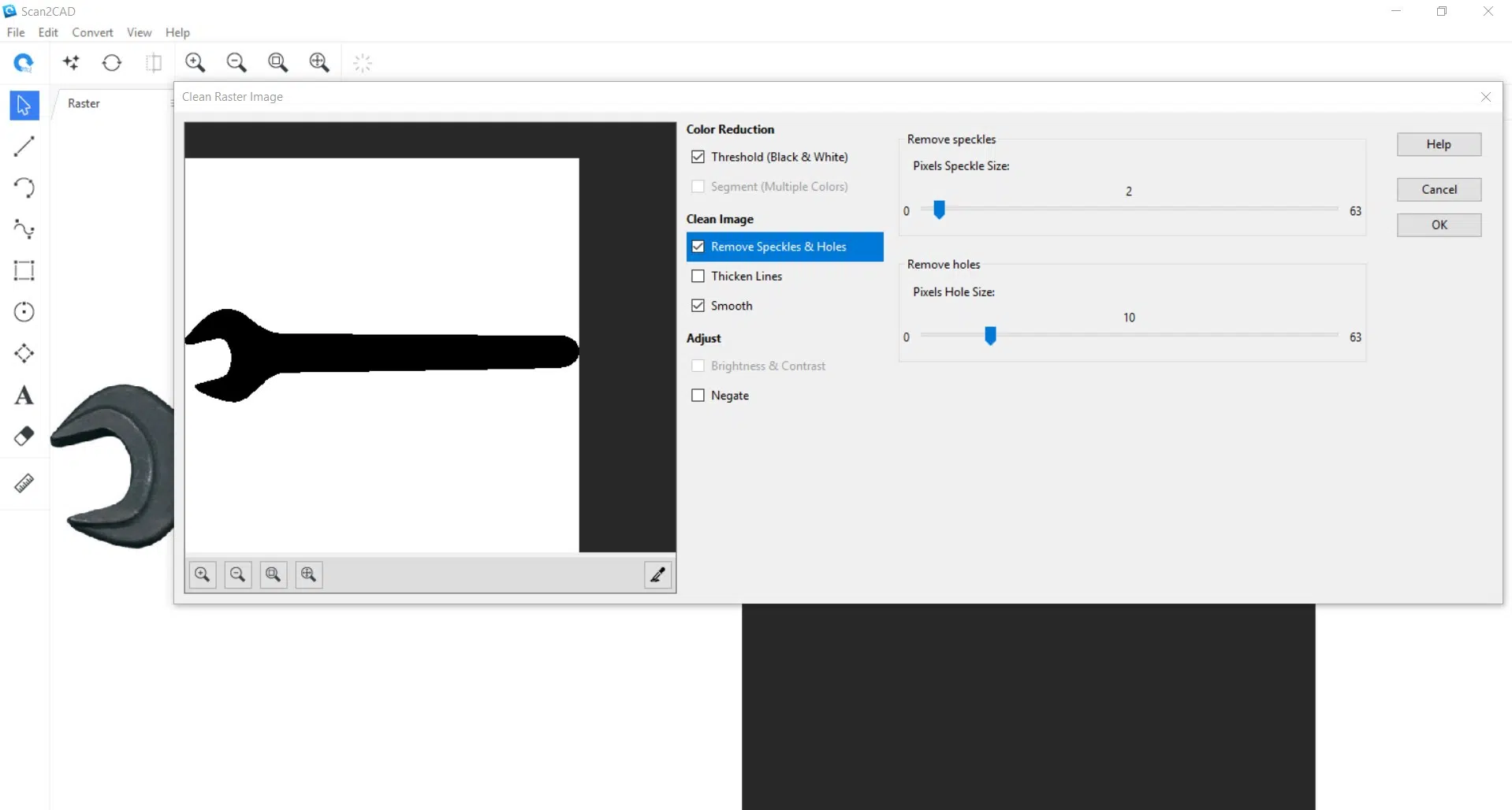
Before conversion, we’ll have to clean up the raster image a little bit. Just click on the Clean Image button by the upper left part of the interface with the symbol that looks like three stars. It’s not too long of a process, but this is where all of the considerations we had in the previous step start to pay off.
Threshold
This basically turns the image completely black and white. If the image we used has high contrast with its background, has no shadows, and is parallel to the surface with little distortion, what we’ll get is a solid silhouette of the tool.
Remove Speckles & Holes
Tick this box if you see some small unwanted white or black lines or marks in the image preview. Speckles are black marks while holes are white ones. Adjust the sliders accordingly, but be careful not to set them too high or the program will start taking out pixels that you actually want to keep.
Smooth
This just helps smooth out jagged edges on the silhouette. You shouldn’t have to worry too much about jagged edges if the photo you used has high resolution, but you can tick this box anyway for good measure.
After cleaning up the image, you can manually do some edits by experimenting with the tools on the left side of the interface. You’ll most likely be using the eraser tool most frequently to erase some unwanted marks you couldn’t take care of before.
Vector conversion

Setting up the conversion
The next step is the actual conversion. There are three vectorization methods available for Scan2CAD, but you’ll only need to focus on Technical and Outline.
If you’ve opted to manually trace around your tool with paper and pen, you’re going to want to use Technical. From the Vectorization Presets drop-down, pick Outline.
If you used an actual picture of your tool to use on this conversion process, pick the Outline vectorization method.
Click on Run first to generate a preview image of your vector conversion. Toggle between the three tabs in the preview box to cycle through your original raster image, the converted vector image, and an overlay of both. You can click on the Highlight vectors button at the lower right of this preview window to see your vector objects more clearly. If you’re happy with what you see, click on OK to run the conversion.
Aside from these Vectorization Methods, there are a bunch of settings in the Convert Image dialogue box that you can play around to get different results. However, if you’ve picked a suitable source image and cleaned up the image correctly in the first steps, the default settings are more than good enough to get you a clean vector conversion
Post-edits and Scaling
We’ll need to do some final touches before we export our converted vector file. Just as we did with the source raster image, we can also use the tools at the left side of the interface to do some minor edits to the vector image. These are only for minor edits though; anything big you want to do with the vector file would be easier to do on a dedicated CAD program so just leave the final big edits for after the Scan2CAD conversion process.
Scaling might be something you want to do before exporting the vector image. We have a full guide available here (https://www.scan2cad.com/learn-v10/#technical-drawings-scaling) for more information.
Saving the image

Saving your file
Finally, the only thing left would be to save the converted vector file. There are a bunch of different file formats you can choose from and picking the format depends on what you want to do with the exported file.
The DXF and DWG formats are most suitable for users who want to do major edits on their vector files with their preferred CAD software. The G-code formats are suitable for those that want to use the resulting vector files directly on their CNC machines or printers.
