Formerly known as CATI, CATIA– Computer Aided Three-dimensional Interactive Application is a family of CAD applications for CAD, CAE, and product life management. It was released by Dassault Systems in 1977. The software is mainly used by Mechanical Engineers, Fluid Engineers, Electrical Engineers, Systems Engineers and Designers. There has been the release of various versions of CATIA through the years, having CATIA V5-6 as the latest version which was released in 2019 and will be used in this tutorial.
Getting to understand how to effectively navigate and use CAD software applications with a plethora of features and tools such as CATIA is quite difficult. To make the learning curve easier, Scan2CAD creates comprehensive guides that would help acquaint you with the basics of CAD software applications in just one hour.
In this article, we would be looking at CATIA’s capabilities, features, and tools available. We will also talk about its graphical user interface (GUI) and the basics of modeling.

Table of Contents
CATIA’S CAPABILITIES
To understand a software application, the first thing you must know is what the software can do, that is, its capabilities. These capabilities can be classified under Mechanical Engineering, Systems Engineering, Electrical Systems, Fluid Systems, and Design.
Mechanical Engineering
The design of parts of assemblies has been made so easy by CATIA as it provides tools for the formation of 3-dimensional elements, 2D drawings, and sheet metal.
Systems
CATIA’s engineering solution gives a detailed open development platform that covers various disciplines. Disciplines like simulation, modeling, verification, and business process support.
Electrical Systems
The software’s V5 version offers electrical schematic definitions, requirement capture, and also interactive 3D routing of wire harness and industrial cables. With this capability, there is no longer the use of physical prototypes as designs are done in the context of full production, therefore reducing the cost of production.
Fluid Systems
The manufacture and design of routed systems like piping, tubing, and HVAC have been made easier with CATIA V5. The software offers a platform for specification-driven design tools that make them up to industry standards.
Design
With the ICEM surfacing technologies embedded in CATIA, the design toolset offers solutions for designing various shapes, styling, visualization, and for surfacing workflow.
Before You Get Started
As we now know what Catia can do, we would need to get familiar with some things before going to the Graphical User Interface. CATIA has 5 main file formats; CATPart used for the design of parts with the .CATPart extension; CATProduct, used in assembly design with the .CATProduct extension; CATDrawing with the .CATDrawing extension; cgr (for faceted representation) with the .cgr extension; and 3dxml (lightened representation) with the .3dxml file extension.
Launchscreen
After launching CATIA, you first come in contact with the launchscreen. The launchscreen is relatively straightforward compared to other CAD software.
At the top left corner of the screen is the menu bar. The menu bar contains the start menu, which is used for selecting applications such as part design, product structure, assembly design, and others; the file menu, used for the creating, opening, saving, and printing of files; the view menu, for displaying workbench specific toolbars and list of commands which would be mentioned later in the article. You can also find the windows menu used in changing to your desired windows; the help menu is very useful in understanding CATIA. It provides a ‘getting started’ guide with different informations on workbenches, products, and solutions.
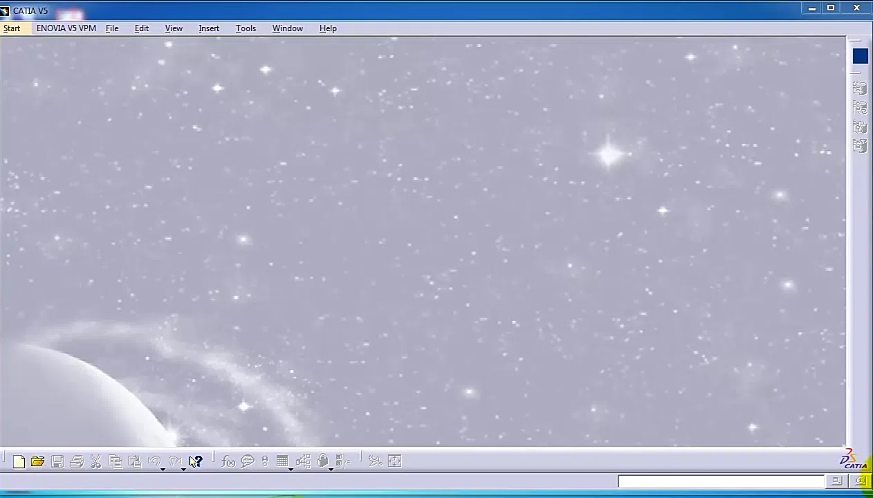
CATIA’s Launchscreen
Getting Started
CATIA offers several applications/workbenches such as part design, assembly design, drafting, sketcher, wide frame and surface, and others. The interfaces of these applications are somewhat similar to each other. For the tutorial, we are going to be using the party design application. The part design application is used in the creation of precise 3D models of machine parts.
Now we are going to open a new part document. To do this, we go to the menu bar and click on the file menu. You then see different options like new, open, close; click on new. This opens a dialogue box showing different document types (drawing, part, product, assembly). Select the part document type and click OK to confirm your selection. After this is done you should enter the part name that you want to be displayed, in this case, part 1. Enter OK again to confirm the part creation. Another way of creating a new document is by going to the start menu. Select the mechanical design then click on the part design to create the part document. As these have been done, the next thing to do is to set the units. To set the units, click on the view menu and select options. After that, click on general. Then parameters and measurements. Your units can be set there.
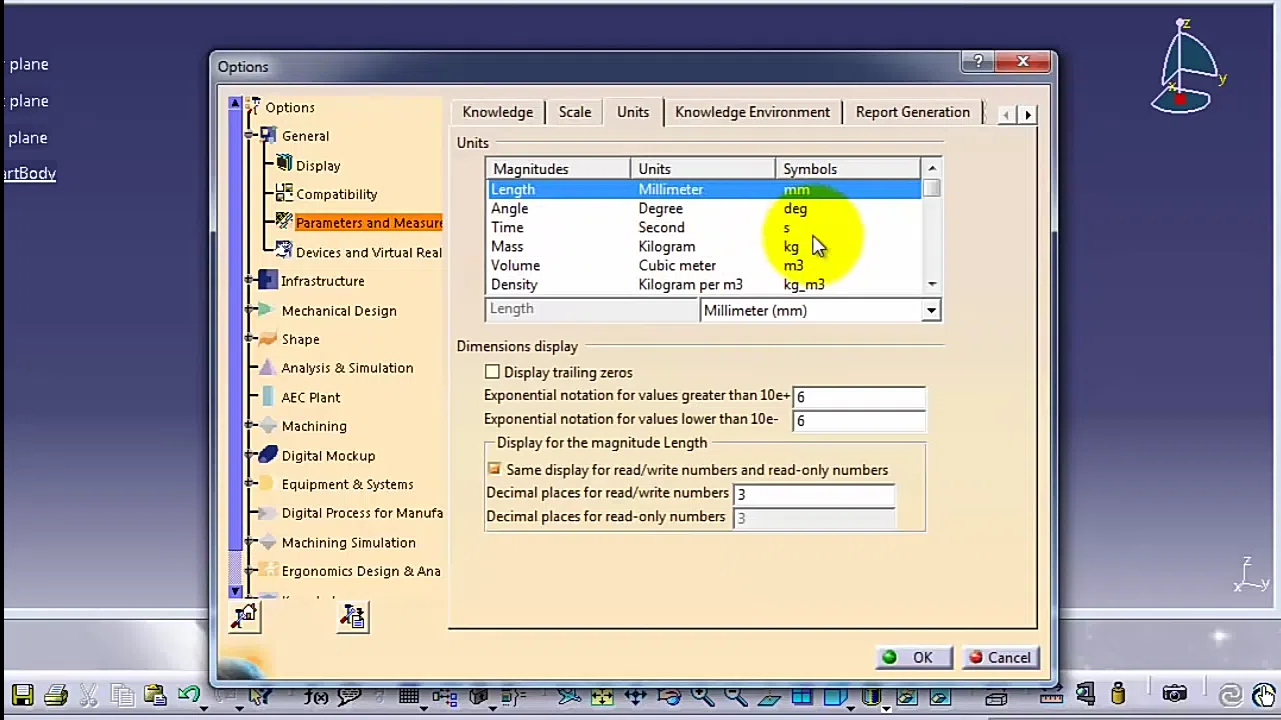
Units dialogue box
Part Creation Window
The part creation window is somewhat similar to that of the launchscreen. At the top of the window the name of the part that you imputed. Directly below the part name are drop-down menus. The drop-down menus contain all the application controls that would help you in performing tasks such as modifying options, file manipulation, changing windows, editing, getting help, and so on.
Below this menu bar is the specification tree. Also called the history tree, it helps you neatly organize and record every part you create using the parent-child relationship. It eases future modification of parts.
The mid-section of the screen is the drawing area. This area occupies about 60% of the part creation window and is where the main modeling is done. Below the drawing area are some shortcuts to various tools such as save, new file, view tools and others. You will also find a tooltip bar that displays messages whenever the cursor is above a tool.
At the right hand of the screen are various toolbars. These workbenches are given in accordance with the current application chosen. At the top right is an icon of the application opened (part).
Then there is the sketcher toolbar, used for the creation and constraining of 2-dimensional geometries. This toolbar has sub-tools under, they are: profile toolbar, used in the creation of geometries like rectangles, circles, lines, splines, and others; the constraint toolbar, used when constraining your with dimensional or geometrical constraints such as distance, length, angles, tendency coincidence, parallelism, and perpendicularity; operation toolbar, used in modifying the profiles created with commands such as trim, mirror, and other commands; sketch tools toolbar, used when you want to work in different modes like shape to point and construction geometry.
The pad toolbar. This is used for adding material in the third direction asides that of the sketch. The creation can be done by extruding an open or closed profile. Specified data can also be added to modify the pad.
Below that is the pocket toolbar. The pocket toolbar somewhat has an opposite function to that of the pad. It is used in removing the material of an already created part.
The shaft toolbar is for making shaft-like parts like an Axel or a drive shaft. In the creation, an axis around which the sketch will revolve is needed.
After that is the rib toolbar. This toolbar adds material alongside a guide curve already created by you. Used in the making of parts such as springs and pipes.
Then there is an advanced extrusion toolbar having sub toolbars, stiffener, and solid combine.
It should be noted that these toolbars can be selected and edited from the view menu in the menu bar at the top of the screen.
Part creation window
Drawing and modeling
Now that you are acquainted with CATIA’s interface and how to open a new document, let’s go to the drawing proper. Modeling of any part on the software must start with a sketch, no matter how complex the part may be. For the sake of this tutorial, we are going to model a pipe. To begin, you click on the sketcher toolbar. Then you choose the plane at the drawing area on which you want the sketch to be. As soon as you select your plane, the different sketcher toolbars are displayed. Click on the profile toolbar and select the circle. You then click on the center point of the plane and drag out to form the circle then click again. After that, click on the constraint toolbar. A constraint dialogue box appears. Set a diameter 80mm then click OK to confirm the selection. When this has been done, exit the workbench and go ahead to click the pad toolbar. Set your depth (90mm) in the pad definition dialogue box that appears on the screen. Since it’s a pipe we are modeling, we would need to have a smaller circle for the hollow. Go back to sketch and follow the same process for creating the circle but with a smaller diameter of 60mm. With this done, click on the pocket command and set the depth which should be the same as the pad depth.

Recommended resources
Being a highly advanced software with numerous packages and capabilities, CATIA is mostly used by professionals. You have now been acquainted with the basics of the software which is a solid foundation to becoming a professional user. To further your learning and mastering of CATIA, we have provided you the following links.
Tutorials Engineer YouTube channel
Solid professor CATIA tutorial
