GeoTIFF is a powerful file format, allowing users to attach georeferencing data to high-quality images. It’s possible to embed GeoTIFF files into GIS applications for illustrative purposes. However, to use them in CAD, or for broader purposes in GIS, you’ll need to convert your GeoTIFF files.
In this article, we’ll run through the reasons why you should consider converting from GeoTIFF to CAD file formats, in addition to a guide to the conversion process itself. So, if you’re a CAD or GIS user and want to put your GeoTIFF files to use, then read on!
About GeoTIFF
Converting a GeoTiff to CAD with Scan2CAD
It’s impossible to discuss GeoTIFF without talking about the format on which it is based: TIFF. The ‘T’ in TIFF stands for Tagged, and refers to the ability to attach metadata to your image in the form of tags. Additionally, TIFF is an extensible file format which gives programmers the freedom to add relevant tags for their work. As a result, TIFF files may include a wide variety of different tags.
The benefits that come with such flexibility, however, come with a price: compatibility issues. After all, users could not reasonably expect all programs to support every possible tag and extension. To combat this, a set of Baseline TIFF Tags exist as a common denominator that all TIFF readers should support.
Some programs do still wish to accept extra tags, though—and to make compatibility and collaboration easier, developers have created a number of extensions to the basic TIFF format. Amongst these is GeoTIFF, which is an extension of TIFF that allows users to include georeferencing data inside those tags.
A wide range of cartographic, GIS, and other organizations worked together to define the tags that form part of today’s GeoTIFF file format. Examples of data within a GeoTIFF file include:
- Geographic coordinates
- Map projection properties
- Coordinate systems
- Ellipsoids
- Geodetic datums
Be aware, however, that not every program will necessarily support or use all of GeoTIFF’s tags. For more information, check out the full list of GeoTIFF tags.
Why convert from GeoTIFF to CAD?
 |
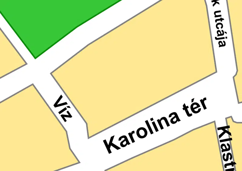 |
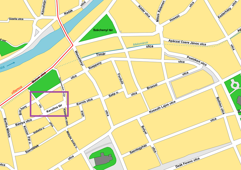
| The image on the left is a vector map of the city of Cluj-Napoca, Romania. On the right is a zoomed-in section of the map, which has maintained its quality. | |
Despite the difference in tags, GeoTIFF is very similar to its parent format. Both allow the storing of high-quality raster images, either with or without compression. As such, many of the reasons to convert GeoTIFF to CAD formats are the same as those for converting from TIFF to DXF:
- As a raster image format, you can’t zoom into or scale a GeoTIFF file without suffering pixelation and loss of quality. Converting to a vector format, meanwhile, allows for infinite scalability.
- A further disadvantage of raster images is their lack of structure. Vector formats, on the other hand, allow users to edit each line or object individually.
- While GeoTIFF files allow users to attach data to an image in the form of tags, it is not possible to attach data to individual elements within that image. When you convert your GeoTIFF to DXF or DWG, you can associate each element of the image with a complex set of properties.
The specific nature of GeoTIFF, however, adds several more reasons. Firstly, GeoTIFF’s georeferencing data means that it has applications in GIS programs. A GeoTIFF image may, for example, serve as the backdrop to a map system.
However, converting to a CAD format, such as DXF, gives the user greater possibilities. That’s because CAD formats allow you to use your image as more than a simple backdrop, but as a way of displaying and contextualizing more information. The range of vector entities lend themselves to different cartographical features: polygons for area measurement; lines for features such as roads; points for individual locations.
CAD file formats
Choosing to convert your GeoTIFF to a CAD file format gives you the option to use your images in both CAD and GIS programs. This allows you to use your image for both mapping and surveying purposes and for various BIM applications. Additionally, many GIS programs will accept CAD formats, while the reverse is not always true.
Two of the most common CAD file formats are DWG and DXF. Both share many attributes common to all vector formats, including scalability and ease of editing. However, there are still some points which distinguish the two from one another. Read on to learn the differences between the two formats, and why you may choose to use them.
DWG
![]() The history of DWG stretches back to the 1970s, predating the program with which most users associate it: AutoCAD. Its status as AutoCAD’s native format, however, is what turned it into a behemoth; DWG is now reckoned to be one of the most popular CAD formats (if not the most popular) in the world.
The history of DWG stretches back to the 1970s, predating the program with which most users associate it: AutoCAD. Its status as AutoCAD’s native format, however, is what turned it into a behemoth; DWG is now reckoned to be one of the most popular CAD formats (if not the most popular) in the world.
Though primarily known as the native file format for AutoCAD, it’s possible to view DWG files using many different programs. Amongst these are some of the most popular GIS programs on the market, including ArcGIS. DWG is also a common file format across a range of Autodesk software, such as Revit.
DXF
![]() Standing in comparison to the proprietary format DWG is DXF. An open standard, the intent behind DXF was to enable collaboration between users of different CAD programs. Indeed, virtually all CAD software on the market today includes built-in support for DXF, and the format remains extremely popular.
Standing in comparison to the proprietary format DWG is DXF. An open standard, the intent behind DXF was to enable collaboration between users of different CAD programs. Indeed, virtually all CAD software on the market today includes built-in support for DXF, and the format remains extremely popular.
Though DXF lacks support for some object types which are specific to AutoCAD, it remains a useful format due to its wide compatibility. Meanwhile, CAD programs are not alone in supporting DXF: GIS programs will generally allow DXF imports, too. This means that it’s not only great for teams working with different specific programs, but that it also allows for cross-disciplinary collaboration.
How to convert from GeoTIFF to CAD
If you’re familiar with converting other raster image formats to CAD, you’ll know that the process is complex. That’s because raster and vector images have entirely separate structures, with the result that the conversion process actually involves creating a vector representation of what appears in a raster image.
There are two ways to achieve this: manual and automatic tracing. Manual tracing is exactly what it sounds like: using a mouse or graphics pen to physically draw vector lines atop an existing raster image. Scan2CAD, on the other hand, offers automatic tracing, which allows a user to complete the process in a matter of seconds.
If you’ve ever read up on our other conversion guides—such as our ultimate guide to TIFF to DWG conversion—you’ll be up to speed with the ins and outs behind the vectorization process. However, there are a few specificities you’ll need to look out for when converting GeoTIFF files.
What makes GeoTIFF different?
When converting most raster image formats, the user is primarily aiming to convey the contents of the image itself. With GeoTIFF, however, it’s important to preserve some of the georeferencing metadata as well as the image itself.
Unlike many online converters, which offer only simplistic solutions (and come with a number of problems), Scan2CAD gives users professional, accurate vectorization results. As part of this, Scan2CAD also uses the following GeoTIFF tags:
- ModelTiepointTag
- ModelPixelScaleTag
- GTRasterTypeGeoKey : RasterPixelIsArea
When opening a GeoTIFF file in Scan2CAD, you can access the georeferencing information by navigating to File > Vector > Export Scale Settings. A dialog box will then appear, such as the one shown below.
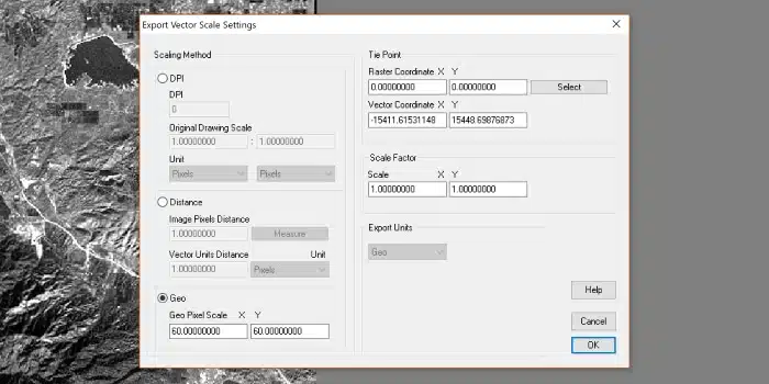
The Geo option appears in the Export Scale Settings dialog box when opening a TIFF file with georeferencing data
In this box, the Geo option will appear, and there are spaces for a number of relevant details. Firstly, Geo Pixel Scale gives information on the distance represented by each pixel on both the X and Y axes.
Then, under the Tie Point option, you’ll see options for Raster and Vector Coordinates. The Raster Coordinate refers to the location within the raster image of a known point; in the example above, this is 0,0. The Vector Coordinate, meanwhile, is the real world location of a known point.
Converting GeoTIFF to CAD
Actually converting your GeoTIFF file to CAD using Scan2CAD could hardly be simpler. Here’s a quick step-by-step guide of how to convert your file:
- Open your GeoTIFF file in Scan2CAD by clicking File > Raster > Load.
- Put your raster to the test by comparing it to our Raster Quality Checklist. If you spot any issues, use Scan2CAD’s range of raster cleanup tools to be sure of a great quality vector image.
- Use the Export Scale Settings menu to ensure you have the correct Tie Point between the raster and vector coordinates.
- Apply one of Scan2CAD’s vectorization settings. This ensures that Scan2CAD processes your image using appropriate settings, and gives you a great chance of better end results.
- Click to convert your image! In just seconds, you’ll have a usable vector image. Simply export the file as either a DWG or DXF to finish.
Using CAD file formats in GIS
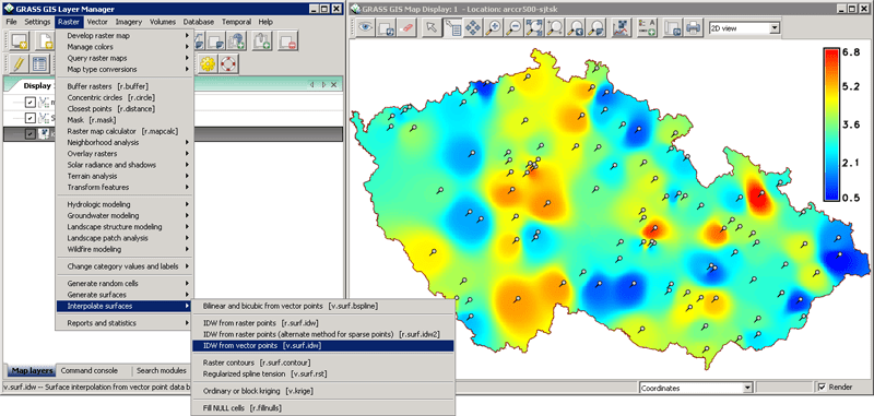
A screenshot of GRASS GIS, an example of a Geographic Information System
After converting your GeoTIFF using Scan2CAD, you’re free to use the resultant DWG or DXF file in the program of your choice. For many users, this means their GIS of choice.
Luckily, most major GIS programs support both DWG and DXF. Be aware, however, that it’s common for such programs not to support the most recent versions of DWG. ArcGIS, for example, supports DWG up to the 2010 version.
In the table below, you can see which common GIS programs support DWG and DXF.
| GIS | DWG supported? | DXF supported? |
| ArcGIS | ✓ | ✓ |
| QGIS | ✓ | ✓ |
| GRASS GIS | ✘ | ✓ |
| MapInfo Pro | ✓ | ✓ |
| Global Mapper | ✓ | ✓ |
| GeoMedia | ✓ | ✓ |
| Manifold System | ✓ | ✓ |
| AutoCAD Map 3D | ✓ | ✓ |
| SAGA GIS | ✘ | ✓ |
| gvSIG | ✓ | ✓ |
It’s also worth noting that some programs (such as gvSIG) allow for DWG imports, but not exports. As such, it’s probably a safer bet to use DXF for your conversion if you plan to collaborate with numerous stakeholders. Nonetheless, as is evident from the table above, wide support exists for both CAD formats. So, if you’re looking to convert your image to vector for use in both CAD and GIS programs, the answer is clear: convert your GeoTIFF file to CAD using Scan2CAD, the ultimate vectorization software.
