BricsCAD is used by structural, mechanical, and civil CAD drafters and modelers. Compared to most CAD programs, it is easier to learn and this guide will help you learn BricsCAD basics in one hour.
In this guide, we shall take a deeper dive into how to use BricsCAD to help you learn the basics in one hour.
Table of Contents
What Can BricsCAD be Used for?
In the beginning, BricsCAD had been designed to be an AutoCAD alternative. However, it has evolved to become a much more capable CAD program with many unique features.
Besides being a great 2D drafting CAD program, BricsCAD fully integrates Parabuild, a detailing package for drawing parametric 3D steel structure models, to automate the process of drawing 3D structural steel models and automatically generate various outputs like CNC data and shop drawings.
Various BricsCAD editions are offering various functionalities. If you are a mechanical CAD drafter or engineer looking to make 2D drawings, you should use the BricsCAD shape, which is free, or the BricsCAD Lite which offers more functionalities compared to the BricsCAD shape.
If you are a mechanical CAD drafter or engineer looking to create 3D models, you should go for the BircsCAD Pro or BricsCAD mechanical.
If you are a civil engineer, structural engineer, or architect, you should go for the BricsCAD BIM.
BricsCAD offers the following functionalities:
- Viewing and managing DWG CAD drawings
- 2D drafting
- 3D modeling
- Parametric modeling
- Annotation
- Printing and plotting
- Rendering
Key Elements of BricsCAD User Interface
To learn BricsCAD basics, you have to first understand the key elements of its user interface.
In this guide, we shall use the user interface of the BricsCAD ultimate, which combines the functionalities of all the other BricsCAD editions.
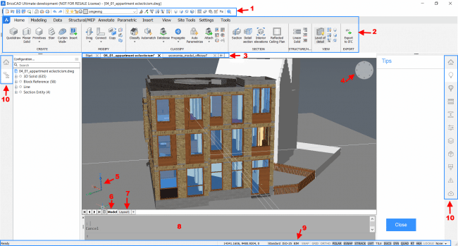
Figure 1. BricsCAD Ultimate user interface elements
The above screenshot shows the user interface of BricsCAD Ultimate and the various sections of the interface have been numbered. Let us take a look at what each of these sections is used for.
Toolbar
This shows the collections of buttons of the most used tools. BricsCAD Ultimate has several toolbars since the edition contains all the functionalities of all BricsCAD editions.
The “Access 3D” is the toolbar that is selected by default.

Figure 2. The Access 3D Toolbar
To choose a different toolbar, you should right-click in the drawing area, then click on choose toolbars to select the toolbar and the related topics you want to use.
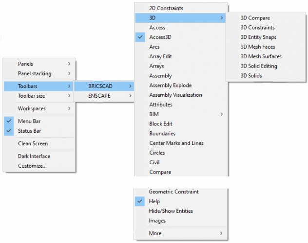
Figure 3. Process of choosing a different toolbar
Ribbon
This shows several tabs containing a series of panels containing organized tools

Figure 4. Tabs

Figure 5. Series of panels
By default, the home tab is selected and the create panel is open. To select any other tab, simply click on the tab to use the series of panels therein.
Customizing the Ribbon
You can customize your ribbon to add custom-made tabs with a label, title, and ID of your choice, edit or expand the existing tabs, create a new panel and also edit or expand the already existing panel. To do so, simply right-click, click on customize and click on “Ribbon Tab”.
It is important to note that the tabs and tools contained in the panels depend on the selected workspace. The workspaces are the ones that define the settings and preferences of the specific working environment.
Selecting a Workspace
BricsCAD has six workspaces which include drafting, drafting (toolbars), modeling, modeling (toolbars), mechanical, and BIM.
To select your preferred workspace, simply right-click, click on Workspaces, and select your workspace of choice.
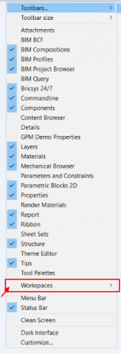
Figure 6. Choosing a workspace by right-clicking
Similarly, you can go to the status bar (labeled 9) and click on the current workspace (in our interface screenshot the current workspace is “BIM”), and select your preferred workspace from the dropdown list.
Document Tabs
This shows the documents that you are working on and it allows you to easily switch between the documents, close a document or even add a document.

Figure 7. Document tabs
To add a new document, simply click on the + sign at the end to the right.
To close a document, click on the X.
The “Look From” Widget

Figure 8. The Look From Widget with no 3D model selected
This appears at the top right corner of the drawing area.
It is used to see how your 3D model would look like when looked at from different angles.
It has seven small triangles and one rectangle along its circumference.
The rectangle shows the side from which your selected 3D model is being viewed in the drawing area. (If there is no selected model, then there will be eight small triangles)
To view the 3D model from a different angle, simply click on a triangle on the angle you want to view from. It also displays the name of the view at the bottom of the widget. For example, “Top Back Left”.
User-defined Coordinate System (UCS) icon

Figure 9. The UCS icon
This shows the nature of the coordinate system that you are using. If you are doing 2D drafting, a two-dimensional coordinate system is shown and when you are doing 3D modeling a three-dimensional coordinate system is shown.
Model Tab
This shows your initial working area, called Model Space. This is where you create your 2D or 3D drawings. If you select to use the Model Tab, you view and work in the model space.
Layout Tab
Every drawing has at least one layout, which comprises one or more viewports. It is mainly used for ensuring that your drawing is ready for presentation or printing.
Every viewport shows a different part of the drawing at a different scale.
If you click on the “Layout Tab’, you can add the entities required for producing a print copy of your drawing. These entities include title blocks, frames, and legends among others.
It is important to note that the layout tab uses the World Coordinate System. (WCS), which is shown by a W that appears at the coordinate system icon.

Figure 10. WCS appears when in the layout mode
Command Bar
This area has two fields separated by a thin dark line. The upper section shows the previously typed commands and is, therefore, wider while the lower section is where you type the commands and command options (which once executed goes to the field above as previously typed commands).

Figure 11. The command bar
Status Bar
It is normally along the bottom edge of the application window and contains information about the settings being used for the current drawing.
It has a total of 16 fields. You can see the list of these fields by clicking the arrow at the right end of the bar.
It is important to note that one of the fields is the workspaces which determine the tools displayed on the ribbon (before customizing the ribbon).

The Tool Panel
This is displayed on the right and left sides of the application window.
Let us look at the functions of each of the displayed icons on the “Tool Panel”.
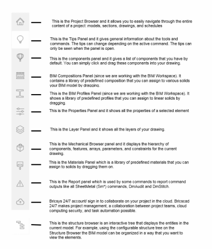
Figure 12. Various panels contained in the Tool Panel and their functions
Learn BricsCAD 2D Drafting Basics
This is the first step in any CAD drawing.
To draw 2D drawings using BricsCAD, you will need to set the toolbar to 2D constraints.
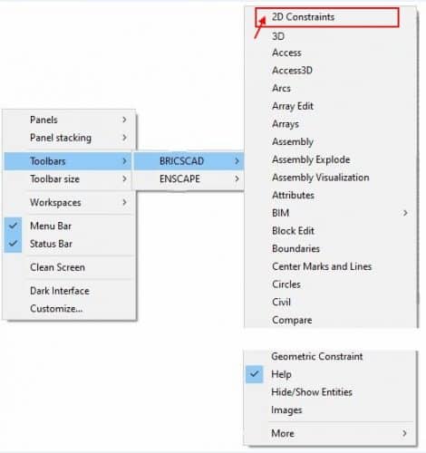
Figure 13. Choosing 2D constraints toolbar
Then change the “Workspace” to drafting or drafting (toolbar).
Once everything is set, you can go ahead and select the tool to use in the “Draw” panel of the Home tab in the ribbon. You can also go ahead to add text, hatching, and dimensions using their corresponding tools from the ribbon.
When you select to use any of the drawing tools or input a drawing command, BricsCAD prompts you to enter the coordinate points in the “Command Bar”. You can choose to use the mouse (clicking on the drawing area and moving to the endpoint) or choose to type the insertion and endpoints.
It is easy to learn BricsCAD since it also displays a context-sensitive prompt menu showing additional command options for the type of entity you are drawing.
Learn BricsCAD 3D Modeling Basics
By default, the BricsCAD Ultimate toolbar is set to Access 3D, which is ideal for 3D modeling. You can also choose to use the 3D toolbar.
Once your toolbar is set to 3D, you should go ahead and select the modeling, modeling (toolbars), mechanical, or BIM workspace depending on the type of 3D modeling you intend to do.
The modeling and modeling (toolbars) workspaces are used for standard 3D models while the mechanical workspace is used for complex mechanical components and assemblies.
The BIM workspace on the other hand is used for Building Information Modeling.
Conclusion
This guide will help you learn BricsCAD basics in less than one hour. With the above information, you are good to start using BricsCAD and make simple 2D drawings as well as simple 3D models.
To sharpen your BricsCAD skills, you should continue practicing with the application as you can see from the above guide, learning BircsCAD is not an uphill task. Besides offering all the functionalities that you may require in your CAD drafting or designing work, the application is very user-friendly.
