If you work with CAD software, you would most likely be familiar with the French CAD development company, Dassault Systèmes. They’re responsible for big names in the CAD and computer modeling industries such as Solidworks and, the subject of this article, CATIA. A common yet nonetheless troublesome requirement for CATIA and any other 3D modeling software is the conversion of raster source materials into workable, editable 3D models. In this post, we’ll discuss some of the most efficient ways to do so.
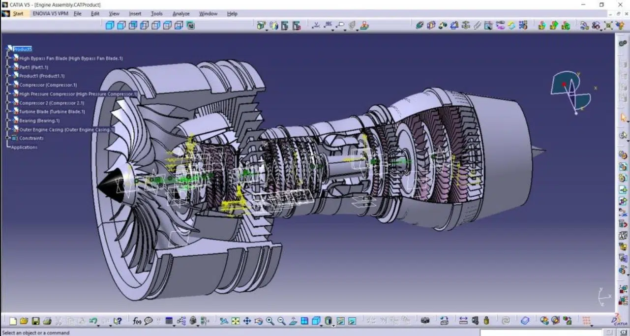
CATIA interface Source
Table of Contents
Supported File Formats on CATIA
CATIA supports both raster and vector file formats. So, what are the types of images (image file formats) you can import into CATIA or convert for use on CATIA? What are the supported vector file formats on CATIA? What other file formats does CATIA support? Let’s find out.
Supported Raster Image Formats on CATIA
CATIA V5 and 3DExperience CATIA support a range of raster image formats, depending on the purpose for which you intend to use the images. Generally, CATIA supports the following image formats:
- PNG
- BMP and BMZ (compressed BMP file)
- TIFF (TIF and TIFF)
- JPG (JPEG and JPG)
- RGB
- PSD
- GIF
- DIB
- RLE
You can import images to support your drawing and modeling process via the Sketch Tracer app. Such images help you draw from an existing model or draft. While you can import PNG, BMP, TIFF, RGB, JPG, and PSD images into Sketch Tracer, you cannot directly modify all the file formats within the software environment. You can only manipulate the former five image formats. For PSD images, you must first create a specific object type in CATIA to modify it. To put it simply, you cannot directly modify PSD images.
If you want to import images for rendering and storytelling purposes, you can only insert JPG, PNG, BMP, TIFF, and RGB file formats. Similarly, CATIA’s Photo to Shape app supports JPEG, BMP, TIFF, GIF, PNG, and HDR images, while the Laboratory Informatics app only allows you to attach PNG and JPEG images. Lastly, the 2D Layout for 3D Design app supports DIB, RLE, and BMZ in addition to the other file formats listed above.
Supported Vector File Formats on CATIA
CATIA supports SVG image files, a vector image format, via the Sketch Tracer app. But like the PSD images, the software cannot directly modify SVG images. To do this, you must first create a specific object type in CATIA, which you can then modify. Through the 2D Layout for 3D Design app, the software also supports CGM, GL, GL2, HPGL2, and PS image/graphic file formats. CATIA also supports other vector file formats in addition to the aforementioned image/graphic file formats. These include native CATIA V5 files (CATPart and CATProduct), STEP, IGES, or 3DXML (the native 3DExperience file format).
In summary, CATIA supports the following vector file formats:
- SVG
- CGM
- GL
- GL2
- HPGL2
- PS
- CATPart
- CATProduct
- STEP
- IGES
- 3DXML
Other Supported File Formats on CATIA
Beyond vector and raster image and CAD formats, 3DExperience CATIA also supports other file formats. This is thanks to its connectors, which enable users to open documents and files created from external software. However, to open these files, you must first import them to the 3DExperience platform. The available connectors include Adobe Acrobat, Microsoft Office: Word, Microsoft Office: Excel, Microsoft Office: PowerPoint, and more. As a result, 3DExperience CATIA also supports PDF, DOC, DOCX, TXT, XML, HTML, XLS, XLSX, and PPT, among others.
Raster vs. Vector File Formats
An important distinction to get out of the way before delving into more specific topics is the difference between raster images and vector images. Any bitmap-based image that’s made of pixels and gets more “blurry” the lower the resolution or the more far in the zoom is a raster image. These include any JPG, BMP, PNG, GIF, and TIFF images. Vector images, on the other hand, are images made of editable “vector” lines, instead of being made from pixels, and are made of specific mathematical instructions and data.
As a rule of thumb, vector files are easier to convert into usable files for any CAD software because more often than not, CAD files are vector files in and of themselves – this includes the files natively handled by CATIA. The processes to convert raster images into usable vector files for CATIA are slightly more complex to handle and will be the main points of discussion in this post. That said, you can also import/insert raster images directly into the CATIA environment and this article will also discuss ways to do this.
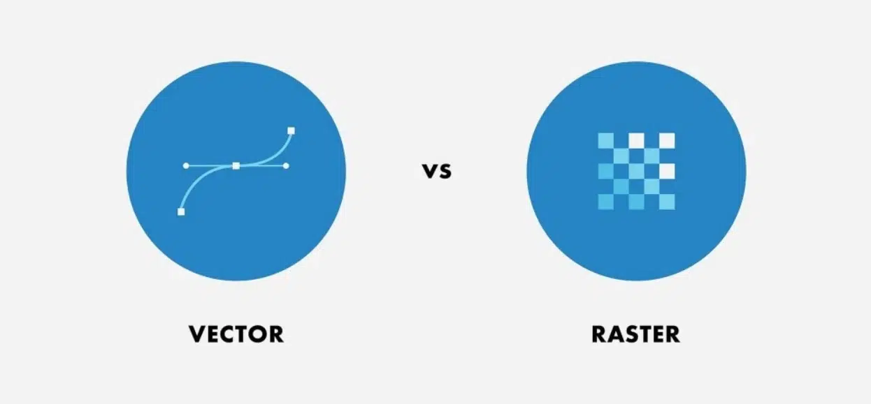
Vector and raster formats Source
Ways to Insert/Import Images into CATIA
CATIA, particularly 3DExperience CATIA, supports numerous ways of importing images into CATIA. This, of course, depends on your CATIA role, which, in turn, requires a particular set of CATIA app. Given that the software supports numerous roles, there are tens of apps on the CATIA/3DExperience platform. (Relatedly, your role(s) and the number of apps you require/need influence CATIA pricing.)
For instance, with the CATIA Laboratory Informatics apps, you can attach PNG and JPG files to text sections of experiments. However, such files cannot be edited as they are only meant to act as file attachments or reference documents. (Laboratory Informatics apps include tools that enable users to create a standardized approach to laboratory processes, such as the management of laboratory workflows and tasks, resources, recipes, and procedures.)
You can also import image files for the purpose of creating rendering and storytelling images. This is possible when using Rendering and Storytelling apps, which enable you to present and showcase your products as photorealistic rendering, for instance. Such images are meant to be referenced by one or more objects in an experience. However, you cannot import every image you have on your computer; the images you import using the Rendering and Storytelling apps must be associated with an engineering document.
3DExperience CATIA’s Photo to Shape app also lets you insert images into CATIA. This app is used to build 3D models of objects from 2D photographs. More specifically, it lets you draw 2D shapes based on the contours and hard points of photographs. It also enables you to create 3D shapes and extract textures from photographs for a realistic visualization. Without going into more details, the Natural Sketch app and the 2D Layout for 3D Design app also let you insert images into the CATIA workspace.
This article will, however, focus on inserting images into CATIA using the Sketch Tracer app. This app is used to import 2D images into a 3D scene and is available in both CATIA V5-6R and 3DExperience CATIA. It lets you convert 2D images into a 3D scene, using the image, which can be a picture or hand drawing, as the basis for a work area. The app also enables you to position the 3D model relative to the 2D image and trace the sketches, i.e., create geometric outlines directly over the sketches or the layout of objects in the image. In this regard, the Sketch Tracer app is an example of a manual raster-to-vector conversion tool.
What are Your Options When Inserting and Converting an Image for CATIA?
Option 1: Using a Built-in Conversion tool or a Third-Party App
|
Pros |
Cons |
|
– Efficient and time-saving – Accurate with quality images – Can handle larger volumes of conversions – Can output several vector types and can open different input file formats |
– Output will only be as good as the quality of the input – Paid (for quality software) |
Some software have built-in raster conversion tools that will automatically trace over any imported raster images with their vector tools. Unfortunately, CATIA is not one of those programs that have a built-in conversion tool. On the bright side, there are amazing third-party apps that can handle that conversion and output vector files that can be easily opened on CATIA.
One such program is our very own Scan2CAD. Scan2CAD can handle both raster and vector source files and is specifically designed to output the best quality vector files that can be used in all standard CAD and modeling programs. That includes CATIA. However, do note that while you can import DXF or DWG files in CATIA, you cannot directly manipulate them within the software environment. Instead, CATIA allows you to use them as sketches. The DXF or DWG files appear as sketches in the CATIA work area.
How to Convert an Image for CATIA Using Scan2CAD
Here are the steps to convert an image into a DWG or DXF file using Scan2CAD for easy manipulation on CATIA:
- Open up the raster image you want to work with on Scan2CAD. The software can handle most standard raster and vector formats.
- Clean up the raster image to make it suitable for conversion. You can go ahead and use the Clean Image button at the top left. You’ll want to use Threshold to turn it black and white, and depending on the image, you can play around with the different tools under the Clean Image menu.
- Scan2CAD also has some nifty editing tools on the left side of the interface. For editing, the erase tool will be your best friend.
- You can go ahead and click the Convert Raster Image button next to the Clean Image tool. Different types of drawings will work better with their own conversion settings, but the default settings are usually good for your typical technical drawings. You can cycle through the Vectorization presets to find the setting most suitable for your drawing.
- You can also opt to use Vectorize and OCR to use the OCR function of Scan2CAD that aims to convert any raster text into TrueType text – text objects that are editable.
- Click on Run to generate a preview and OK to finalize the conversion.
- You can once again use the tools on the left to do some final edits on your converted vector file.
- Click on File > Save As > Vector. Locate the location you want to save your new file in and pick the vector format you prefer (DWG and DXF work best for CATIA).
Option 2: Manually Drawing Over (Tracing) the Image
|
Pros |
Cons |
|
– Highly accurate (depending on the individual drafter’s ability) – Free – Tried and tested method |
– Time-consuming – Inefficient – Prone to human error |
Before the advent of CAD, the main way to reproduce and edit any existing technical drawings was tracing over them with tracing paper. In the digital age, CAD users emulate that by overlaying vector lines over any source raster image they choose to use. As it was was before, the process can be painstaking and tedious but some users prefer using this tried and tested manual method over automatic conversion processes.
The main reason these users opt for manually tracing is the belief that a high degree of accuracy is not possible with conversion software. This stigma against automatic conversion is probably exacerbated by the results you can get from free automatic conversion software available online. However, dedicated apps used for conversion have the advantage of continually developing technologies used for CAD and can compete with almost any manual tracing when it comes to accuracy at a fraction of the time. This makes it a better option in the majority of cases.
However, they do have limitations when it comes to source images with low quality. Either the scan wasn’t done properly or the resolution is simply too low. In these cases, manually tracing will have to suffice when it comes to recreating these low-quality images.
Working with CATIA V5
In this case, if you’re dealing with a 3D object you need to model on CATIA the steps would be the following:
- You’ll need to procure suitable images for tracing. If it’s a 3D model, try to get technical drawings of the top, front, and side views of the model. These will make tracing and modeling much easier in the long run.
- Click on Start > Shape > Sketch Tracer. In the new window that opens up, choose the first view which you want to import a drawing in. For example, if you want to insert your front view image first, open up the Front View plane. You can access this by clicking on the View pop-up menu typically at the bottom of the screen that has a blue cube icon.
- While on the plane you want to work on, click on Create an Immersive Sketch to the left of the viewing port. Locate and open the image you want to import.
- Move and edit the green Model Axis tool that pops up over the inverted image. Use this to scale and size the imported image just right.
- Repeat steps 3 and 4 with all the views you have image references of.
- At any point, you can open up the properties of these imported images to edit their Transparency or lack thereof to make things easier when you start tracing the images.
- Once you have all your images all scaled and lined up with a transparency level you’re comfortable with, all that’s left is to use CATIA’s drafting and modeling tools to create your model.
Working with 3DExperience CATIA
To insert a single image, follow the procedure below:
- Log in to the 3DExperience platform and launch the Sketch Tracer application by clicking the compass icon

- Drag the image you want to use from its location on your computer to your CATIA work environment
CATIA positions the image on the current drawing plane and resizes it to fit about 1/3 of the screen. - Edit the image as desired by modifying the resolution and opacity
- Use the image as a drawing support for tracing or sketching

To insert multiple images for the various drawing planes, follow this procedure:
- Log in to the 3DExperience platform and launch the Sketch Tracer application by clicking the compass icon
- Tap Image Chooser on the Images section of the action bar at the bottom of the window
This action displays a box representing the 2D canonical views - Select the image you want to use from your computer and drag it onto a plane of the box that corresponds to the view represented by the image, i.e., top, left, right, back, front, and bottom.
- Repeat step 2 for all the other planes
CATIA calculates the dimensions of the image as a ratio of the dimensions of the plane - Edit the image as desired by modifying the resolution and opacity
- Use the image as a drawing support for tracing or sketching
Comparison of Automatic vs. Manual Conversion
|
Automatic Conversion |
Manual Conversion |
|
Automatic conversion is fast/rapid |
Manual conversion takes a lot of time |
|
It only works perfectly with high-quality images |
It can work with both high-quality and low-quality images |
|
Automatic conversion works best with black-and-white images |
Manual conversion can work perfectly with both colored and black-and-white images |
|
This conversion approach boasts high accuracy and precise |
The accuracy and precision in manual conversion are affected by human limitations; for instance, humans’ spatial accuracy level is 40 dots per inch (DPI) at best, which is lower than computers’ |
|
Computers cannot fully understand drawings and images, which can lead to unintended errors |
Humans can fully understand and interpret drawings and images, enabling them to tell exactly what the drawings represent and where the edges should pass |
|
Although automatic conversion is constantly improving thanks to the introduction of new technologies, it is still limited by what such technologies can achieve |
While manual conversion has not improved due to human limitations, the human eye is still better at identifying the outline/borders of models and drawings regardless of the quality of the image |
Frequently Asked Questions
- Are there any specific settings I should be aware of when converting images for CATIA?
If you are using Scan2CAD, save the converted file as a DWG or DXF file. However, do note that even if you use the automatic conversion approach, you will still have to use manual tracing after importing the converted file to CATIA. This is because CATIA does not natively support DXF or DWG files. That said, Scan2CAD comes in handy as it helps you clean the image. - Can CATIA handle colored raster images or does it only handle black and white?
CATIA handles both colored and black-and-white raster images. When working with the 2D Layout for 3D Design app, 3DExperience CATIA automatically sets monochrome pictures to the CCITTG3 format, a lossless compressed data format. This conversion prevents data loss. - What’s the recommended image resolution for a quality conversion?
To import and load images in the Image Board of CATIA’s Photo to Shape app, Dassault Systemes recommends that the images’ resolution should not exceed 24 MP. The recommended resolution is 8 MP. That said, Dassault Systemes does not have a blanket recommendation for the image resolution covering all its apps. - Are there size limitations for the image I can import into CATIA?
The maximum size for an image file attachment (in CATIA’s Laboratory Informatics app) is 25 MB. CATIA also limits to 10 the number of files you can attach. - How does the quality of the original raster image affect the final vector output in CATIA?
CATIA does not perform automatic conversion. Instead, it requires the user to trace the outline manually. And given that the human eye is better than automated tools at picking out geometric objects from dirty images (of course, up to a certain threshold), the quality of the original raster image does not significantly impact the final vector output. - Can I use both automatic conversion and manual tracing techniques on the same image in CATIA?
Yes. This is especially so if you use Scan2CAD. CATIA does not support DXF or DWG files. Thus, you can use automatic conversion (Scan2CAD) to convert a raster image to a DXF or DWG file. Then, you will have to import the DXF or DWG file into CATIA to draw over/trace the layout of the drawing in the imported file.
Conclusion
CATIA is a wonderful piece of software that can be more easily used when using software such as Scan2CAD to streamline the process of conversion. Not only do the two programs work well individually, but they also work amazingly well when used in tandem.
Save time and effort by opting to use software specifically designed for CAD file conversions.
