Though the medium of design has now shifted from the sketchpad to the screen, there are still those who prefer to sketch by hand. Nonetheless, it’s rare to find anyone within the design industry who produces a hard copy of a design without a digital file to back it up. After all, paper drawings are just physical records. Designers and engineers need to convert blueprints to CAD.
This guide covers everything you need to know about scanning a design into the computer, and converting the resulting raster file into a CAD-friendly vector format.
Table of Contents
When would paper to CAD conversion be used?
There are several instances where paper to CAD conversion becomes necessary.
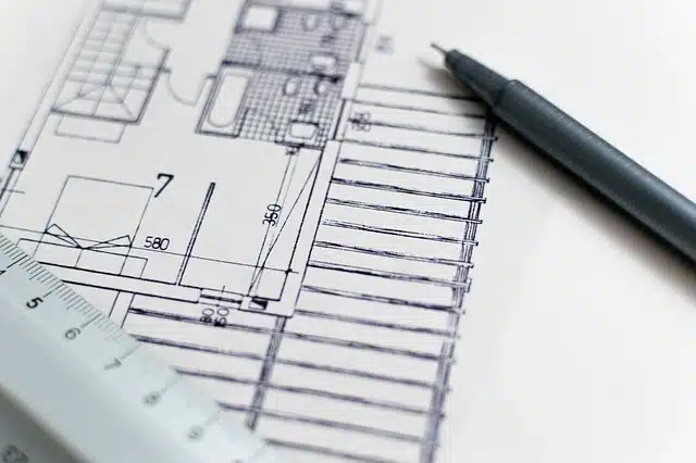
One common scenario involves old technical drawings or architectural plans. Your studio may have won a contract to develop part of a site further. The trouble is, all of the previous plans were drawn on physical paper, rather than on a program like AutoCAD. In such an instance, you could begin by manually drawing the designs in your preferred software, and going from there. However, this would require a huge commitment of time and energy, which would be better spent editing the initial design to the client’s new specifications. A more efficient method would be to use the technological advances that are present in Scan2CAD, which allow you to automatically convert a scanned paper drawing to a CAD format.
The same principle applies to hand-drawn sketches, or any other design that has been produced on paper.
Why do you need conversion software?
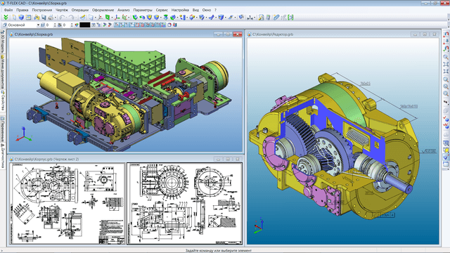
Only vector graphics are suitable for designing in CAD. Source: University of Connecticut
When you scan your drawing—either onto your computer, or directly into Scan2CAD—you will be able to save it as a raster file. Raster file formats are commonly used display on the web, but are not suitable for use within the context of CAD design. Their lack of structure means that you cannot edit individual entities without affecting the image as a whole. Furthermore, if you increase the image size, this can cause the drawing to lose quality and appear fuzzy or pixelated.
In order to use your scanned paper drawings for CAD design purposes, you will need to convert blueprints to CAD compatible vector format, such as DXF (Drawing Exchange Format) or DWG (Drawing). Unlike raster images, vector files are capable of holding masses of data about each individual element. This data is readable by CAD software, and is invaluable when collaborating on an important project.
Vectors also benefit from resolution independence: however far you zoom into the file, you will never see a loss of quality. Furthermore, whereas raster graphics are made up of pixels, vector graphics are made up of objects, such as lines, arcs, Bezier curves or polygons. You can edit each of these entities individually without affecting the rest of the image, granting the designer much more freedom.
There are 2 methods to convert blueprints to digital: manual tracing and automatic tracing. The term ‘tracing’ refers to the process of drawing over raster images with vectors. While humans can understand design more effectively than technology, we’re more prone to inaccuracy. Tracing by hand with a graphics stylus or mouse is also very time consuming. Automatic tracing, on the other hand, is performed by raster-to-vector software like Scan2CAD. You may have to touch-up raster images prior to conversion, but the process is very quick: it takes mere seconds.
With Scan2CAD, you can opt to convert a scanned drawing to a wide range of different vector formats—most commonly DXF or DWG. We’ll look at the differences between the two, and how to vectorize your drawing a little later.
Scanning your drawing
Can you scan any drawing?
Conversion software is only able to work with what it’s given. When assessing whether your drawing is suitable for scanning, you need to be aware of both size and clarity.
Some drawings are simply too small to be scanned, however much you try to offset this with resolution. Others are too faint, or too dirty, to be cleaned up well enough to produce a credible scan. You also need to be aware of obscured lines. If too many lines are overlapped by text, no software would be able to make sense of the information. Therefore if your aim is to convert blueprints to digital, ensure you have a suitable quality drawing and scan.
What type of scanner can you use?
You can scan directly to Scan2CAD: all you need is a compatible scanner. These include any Twain- or WIA-compliant scanner, or, if you have the pro version, a Colortrac SmartLF scanner, or an HP Designjet T2300 eMFP.
Simply start by loading your design directly from your scanner into Scan2CAD. If a dialogue box appears, choose appropriate settings, and then instruct the software to Scan.
It makes little difference which of these scanners is used, although the latter model does offer you a preview within the software; use this to check whether your scan is fit for conversion. If not—if your drawing is skewed, for instance—rescan until the image is optimal.
If you don’t have access to any of the scanners mentioned, you can still convert your drawing to CAD: it will just add a couple of extra steps. Simply scan your drawing onto your computer as normal, load it in Scan2CAD, and vectorize.
When scanning your drawing, it’s important to save it as a lossless format. TIFF is an ideal format; other lossless formats include BMP and PNG. You should avoid lossy formats, such as JPEG, which sacrifice image quality for smaller file sizes.
Scanner Settings
Color
Most scanners give you the option to scan in color, grayscale, or monochrome. In most cases, the best option to convert hand-drawn plans to digital is to scan your drawing in monochrome. This separates your image into just two colors—black and white—which means that Scan2CAD can easily separate out the design in the foreground from the white background.
If scanning an image as a monochrome image, it’s worth checking your scanner’s threshold settings. These determine which parts of your image are scanned as black and white respectively. If they’re set too high, text may “bleed”, and speckles may appear in the background. Set them too low, and your image may lack detail. It’s possible, however, to simply scan your image in grayscale, then separate the colors out into black and white using Scan2CAD’s thresholding tool.
Resolution
High resolution doesn’t automatically produce a better scan; the important thing is to find the resolution that is most appropriate. But you should also be aware that while you can decrease image resolution after it has been scanned, you cannot increase it. As a general rule, you should be looking at a resolution between 200 and 400 DPI; smaller images, such as logos, may require higher resolution. If your scan appears pixelated, this is a key sign that you need to increase the resolution. Likewise with characters within areas of text, and the spacing of entities—you want clear white space to be visible between them.
This latter issue may need a combination of resolution and threshold adjustments, and you should experiment with both until the image is optimal.
Pre-conversion clean-up
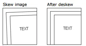
Using the Deskew tool on very skewed images usually results in a significant loss of quality
Before you convert hand-drawn plans to digital, ensure that you have not missed any basic errors. Check that the whole drawing has been scanned and that it is as straight as possible. While Scan2CAD does provide a deskew tool, using it may result in a loss of quality. See our comprehensive guide for optimal raster-to-vector conversion results for more areas you should watch out for.
If you do need to clean up any of the image, there are a number of tools available to you. Other than deskew, you can also fill in missing gaps in lines. Use the Remove Holes function for small holes, or Flood Fill for larger gaps. Opting to Smooth lines will get rid of stray ‘hairs’ from your lines, and if there is a small amount of dirt in the background, you can ‘Remove Speckles’ to eliminate marks.
It’s best at this point to work through the full quality checklist, zooming in to ensure you haven’t missed anything that will become an issue during vectorization.
Converting to vector
DXF or DWG?
To convert from a simple image to a file that contains important design data and that can be easily edited in CAD software, you’ll need to convert your drawing from raster to vector. With Scan2CAD, you can choose between numerous vector formats, notably including DXF or DWG. Both formats allow you to edit individual entities and reuse them, should you so wish. This can save time in the future when creating CAD files with similar elements to those in this file. What’s more, neither DXF or DWG files are resolution dependent: however far you zoom in or out; whatever size you view the image, the drawing’s quality will be retained.
But while DXF files are supported almost universally by CAD programs, making them ideal for collaboration, the DWG format is native to AutoCAD. If you don’t own this software, don’t panic—you may still be able to view and edit a DWG without AutoCAD.
You may prefer this format if you are keen to edit the drawing using native AutoCAD entities, or if you are only going to be sharing the file with those who use the same software. If you are unsure which to go for, take a closer look at the qualities of each of these vector file types. And remember, it’s not the end of the world if you get it ‘wrong’: you can always convert your DWG to a DXF, or vice versa, at a later date.
How to vectorize your drawing
Whether you’re looking to convert your scan from a TIFF or a PDF, and to a DXF or DWG, the process is the same:
- Open the scanned image into Scan2CAD
- Clean the image (if required) using Scan2CAD’s image cleaning tools
- Convert the image using Scan2CAD’s Vectorization and OCR
- Export the converted vector image to DXF or DWG for your CAD software.
It really is as quick and simple as that! And, if you’ve got a mountain of hard copies that you need to scan, there’s no need to convert each one individually. Use the Batch Processing tool to automate the process, while retaining control on pre-conversion optimization.
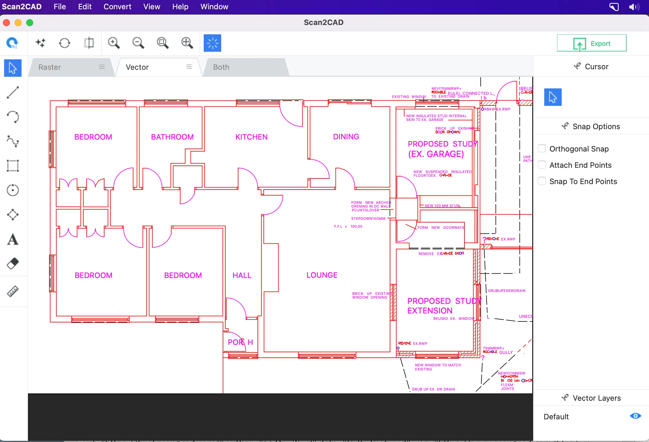
A floor plan drawing converted to DXF in Scan2CAD
What about Paper to CAD Conversion Services?
If converted your paper designs to CAD yourself seems like too much work, you could look into paper to CAD conversion services. These service providers will require you to send them your paper copies and they will subsequently scan and convert your drawings to your required format.
Paper to CAD conversion as a service is not without its issues. In fact, we created an article for those who wish to make an informed decision on whether or not to outsource conversions: CAD Conversion: Do It Yourself Or Outsource? Most notably, outsourcing conversion is not a zero-work option. You will need to consult with the conversion service providing detailed specifications of the conversions you require and you should carefully check the accuracy of all delivered files. Finally, outsourcing is not an option for the majority of companies who have a policy of protecting their client’s drawings.
Useful resources
If you need more support on converting your scan to vector, then you may find the following pages helpful:
- Converting from TIFF to DXF — Your ultimate guide
- Ultimate Guide: TIFF to DWG Conversion
- Ultimate Guide: PDF to DXF Conversion
- Ultimate Guide: PDF to DWG Conversion
- FAQs: DXF Conversion
If you want to have a go at converting a paper drawing to CAD without the commitment of paying, you can enjoy a no-strings-attached, 14-day trial of Scan2CAD without spending a penny. You’ll soon realize why it is the ultimate market-leading vectorization software.
