
As technology evolves and people lean towards aesthetics while still demanding the best functionalities in products, mechanical engineers are faced with the challenge of designing more complex products every day. And as such, mechanical engineers are required to not only select the most powerful CAD software but to also learn how to best use the software to design even the most complex designs. And that is the purpose of this guide; to help mechanical engineers, learn AutoCAD Mechanical, which is one of the most commonly used CAD software used in designing mechanical components.
But before delving into how to use the software, let us first look at what it is and what it can do (or what it can be used to do).
Table of Contents
What is AutoCAD Mechanical?
AutoCAD Mechanical is a software product of Autodesk Inc., which is an American software corporation that makes CAD software for engineering, architecting, manufacturing, construction, education, and entertainment and media industries. The AutoCAD Mechanical software is specifically made for mechanical engineers, manufactures, and designers.
What can AutoCAD Mechanical software do?
Mechanical engineers manufacture, and designers can use the AutoCAD Mechanical software for:
- 2D drafting, drawing, and annotation – this involves producing 2D drawings/drafts, generating dimensions, creating and editing single or multiline text, creating leaders with a variety of content, creating and editing centerlines and center marks, creating tables with data and symbols in rows and columns and applying formulas, linking the tables to a Microsoft Excel spreadsheet, saving views by name, specifying layouts (drawing sheets), creating arrays (objects that are created in circular or rectangular patterns, or along a path), and applying parametric constraints.
- 3D modeling and visualization – this involves creating solid, surface, and meshed realistic 3D models, using 3D viewing and navigation tools to walk, swivel, fly and orbit around 3D models when showcasing designs, applying visual styles, creating section planes to display cross-sectional views, rendering, and generating 2D drawings of 3D models.
- Collaboration – this involves, importing, exporting, or attaching files as underlays in PDF, DWG, or DGN files.
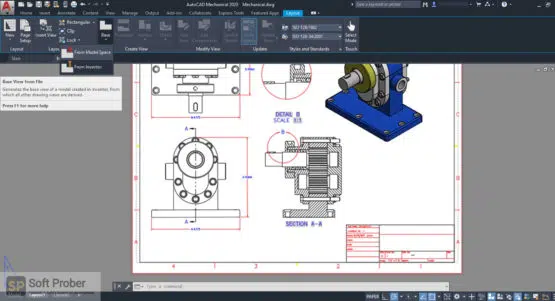
Figure 1. A 2D projection drawing of a 3D model drawn using AutoCAD Mechanical (Source)
We shall look into each of these to assist you to learn AutoCAD Mechanical basics for performing any of the tasks.
Orientation
If you are a mechanical engineer, designer, or manufacturer and want to perform any of the above tasks using AutoCAD Mechanical but you are wondering how to start, this AutoCAD Mechanical: Learn the Basics in 1 Hour guide will take you through all the basics to help you learn AutoCAD Mechanical basics in the least time possible.
We shall start with learning about the various features, and tools that you shall encounter when you open AutoCAD Mechanical software.
When you click to open AutoCAD Mechanical, you should click ‘Start Drawing’ under ‘Get Started’ if you are using a more recent version like 2020 or ‘New’ under the Work section when using older versions like the 2013 version, which we shall use for this guide, to start working on a new project.

Figure 2. Figure 2. AutoCAD Mechanical 2020 start screen

Figure 3. AutoCAD Mechanical 2013 start screen
When it opens, the user interface looks like the one shown in the screenshot below:

Figure 4. AutoCAD Mechanical user interface explained
We shall look at what each of the features and tools that are shown in the above screenshot is used for.
1. Application menu Button – This offers tools for managing your AutoCAD Mechanical files. When clicked, a file pull-down menu appears. The pull-down menu contains buttons for actions such as ‘New’, ‘Open’, ‘Save’, ‘Save As’, ‘Export’, ‘Publish’, ‘Print’, ‘Drawing Utilities’, and ‘Exit’.

Figure 5. Pull-Down menu that appears after clicking on the Application Menu button
2. Title Bar – This is where the name of your current project/drawing is displayed denoting even the format of the file. If you look at the screenshot shown above, the name of the current project is saved as Drawing1.dwg showing it is a .dwg file.
3. Quick Access toolbar – This provides access to some of the buttons found by clicking on the application menu button. By default, this toolbar contains the buttons for opening new tabs, opening existing files, saving your work, save as an option, and the cloud option.
4. Info center – This displays various information like the search results button, sign-in button, Autodesk exchange apps button, stay connected button, and the help center button.
5. Ribbon – This contains sets of drawing and modeling tools that are grouped in various groups. These groups are put under various tabs including Home, Insert, Annotate, Layout, Parametric, View, Manage, Output, Plug-in, Online, and Express Tools. The Home tab contains groups of some of the most common tools grouped into Draw, Modify, Layers, Annotation, Block, Properties, Groups, Utilities, and Click board.
6. Drawing tabs (file tabs) – This shows the opened tabs each representing a different project. You can open as many tabs as you wish and they shall be displayed at the top adjustment to each other in the same way the start and file tabs are in the above ‘AutoCAD Mechanical user interface explained’ screenshot.
7. Drawing area – This is where your current project will appear and it is where you perform your tasks like drawing, modeling, rendering, and so forth.
8. User Coordinate System icon (UCS icon) – This is an icon of AutoCAD’s Coordinate System that tells you the position of the various things including your cursor when drawing. It is very important, especially when working with complex 2D drawings and 3D models.
9. Viewport Controls (In-Canvas controls) – This shows the current view (side and form) of the project you are working on. By default, the viewport controls are set as Top and 2D Wireframe.

Figure 6. Viewport Controls set to Top and 2D Wireframe by default
To view a different side and form of your drawing, just click on ‘Top’ and ‘2D Wireframe’ respectively, and a drop-down list where you can change the default side and form will appear.

Figure 7. Different sides appearing after clicking on ‘Top’

Figure 8. Different forms appear after clicking on 2D Wireframe
10. View Cube – This is used for turning/rotating your drawing or model to view the different sides.
11. Navigation bar – This is used for navigation, panning, zooming, orbiting, and creating and viewing recorded cinematic motions.
12. Command Line – This shows the current action that you are undertaking.

Figure 9. Command-line showing current action
In the above screenshot, we have selected to draw a circle and the command line displays ‘Circle Specify radius of a circle or [Diameter]:’. You can input the value of the circle’s diameter after the full colon and click enter to complete drawing the circle of the specified diameter.
When performing any task, be it to draw a line, a spline, or anything, the command line window will always display what you should do and what inputs you should input by stating the type of input in brackets just as [Diameter] was placed in the brackets.
13. Status bar – contains a range of menus including the workspace switching menu.
14. Workspace switching menu – This enables you to change certain aspects of the drawing area like Infer Constraints, Snap Mode, Orthogonal Mode, Polar Tracking, Object Snap, 3D Object Snap, Object Snap Tracking, Allow/Disallow Dynamic UCS, Dynamic Input, Show/Hide Lineweight, Show/Hide Transparency, Quick Properties, Selection Cycling, and Annotation Monitor.
Making basic drawings using AutoCAD Mechanical
Selecting the units to use
Before starting any project, you should specify the units that you want to use. To do this you should type ‘Units’ (when you type anything it is typed in the command line window and the respective command is displayed. Click enter and select the units you want to use, the length type (e.g decimal, fractional, etc.), the length precision, the angle type, and the angle precision.

Figure 10. Selecting units in AutoCAD Mechanical
For this guide, we shall use inches.
Drawing different shapes
Basic drawing start by drawing different shapes on the drawing area by either using the different tools found in the ‘Draw’ group of tools under the home tab in the ribbon or by typing the name of the shape you want to draw and press enter.
For instance, if you want to draw a line you can click on the line tool 
If you want the line to be at a certain angle, type ’<’ after selecting the start point of your line and input the value of the angle you want and press enter. This will ensure that the line you shall draw by either moving your cursor or input length in the command line will be inclined at an angle of 30.
Once you complete using any of the drawing tools, you should click enter or ‘Esc to exit that tool to select another option
Modifying drawings
To modify any shape that you draw, you can use any of the tools in the ‘Modify’ group of tools under the Home tab in the ribbon. Alternatively, you can type the name of the ‘modify’ action you want to use and click enter and the command line shall direct you on what to do or input.
Some of the most commonly used ‘Modify’ tolls used include Move, Copy, Trim, Stretch, Mirror, and Scale.
For example, if you want to mode a shape or object, type ‘move’ and click enter or click on ‘move’ from the tools in the ‘Modify’ group of tools. As a beginner, follow the commands specified in the command line window.
Adding dimensions, texts, leader lines, and tables to your drawings
To add dimensions, texts, leader lines, and tables on your drawings, select what you want to add from the ‘Annotation’ group of tools under the Home tab in the ribbon and follow the commands specified in the command line window.
Taking measurements of various aspects on your drawings
To measure distances, angles, radius, area, or volume of your drawing in AutoCAD mechanical, simply click on ‘Measure’ in the ‘Utilities’ group of tools under the Home tab in the ribbon and select the type of measurement (e.g. distance) you want to take.
Then follow the commands shown on the command line window.
Saving your work in different CAD file formats
By default, the AutoCAD Mechanical saves files as .dwg files. Therefore, if you click on save you will be saving your drawing as a .dwg file.
To save your drawing in another format, simply click on the application menu button, scroll down to ‘Save As’ place your cursor on the arrow pointing to the right, and select other formats.

Figure 11. Saving drawing in different formats in AutoCAD Mechanical
Then proceed to input the name of your drawing and select the file format in which you want to save the drawing.

Figure 12. Selecting the file type to save your drawing
Saving your CAD drawing as a PDF
To save a PDF version of your CAD drawing using the AutoCAD Mechanical, simply click on the application menu button and scroll down to export and place your cursor on the arrow pointing to the right. Then select PDF and proceed to input the name of your PDF file and the location you want to save it.
