Computer Numerical Control (CNC) machining has reduced the time required to manufacture parts. However, as advantageous as this may seem, it complicates inspection and measurement. Typically, CNC machines produce parts much faster than one can practically measure or inspect them using conventional tools. Nevertheless, inspection and measurement are critical operations that ensure accuracy and adherence to predefined tolerance limits.
Consequently, alongside the automated manufacturing of CNC machining, there has always been a need for an automated approach to measurement and inspection. This requirement gave birth to probing. This article discusses probing in CNC machines, detailing what it is, probing techniques, types of probes, how probes work, and perhaps most importantly, the advantages and applications of probing in CNC machines.
Table of Contents
Understanding Probing in CNC Machining
What is Probing in CNC Machining?
Probing is the use of devices to inspect and measure machined features and/or machining tools. This process can be executed on a CNC machine or a coordinate measuring machine (CMM). In CNC machining, this operation is executed before, during (as in-process inspection), and after (post-process monitoring) the machining process. In-process inspection refers to the practice of measuring or analyzing a produced feature and its dimensional characteristics immediately after it has been machined without altering the process flow. This aids manufacturers in identifying errors early in the production process, thus saving time and money.
However, not all CNC machines can carry out in-process inspection. In such cases, CMMs, which are stand-alone inspection units, are used. They are complex devices that measure the geometry or dimensions of parts and physical objects by locating discrete points on them. However, CNC machines can be retrofitted with additional tools to transform them into CMMs.
It is worth highlighting that probing is not a plug-and-play operation. Rather, one must outfit the CNC machine with a probe and then input lines of code to instruct the machine on how to use it. Neglecting to integrate these lines into the CNC program can result in breakage, as the machine may drive the probe into a workpiece, treating it like any other tool.
Probing Techniques in CNC Machining
There are three main probing techniques in CNC machining:
- Contact or tactile probing
- Noncontact or nontactile probing
- Simulated probing
Contact or Tactile Probing
In contact or tactile probing, the probes touch the workpiece and maintain contact during data collection. This probing technique is favored for working with larger parts, as well as those with complex geometries and features. Hard probes, touch trigger probes, and analog scanning probes are examples of probes that collect data by touching workpieces or parts.
Noncontact or Nontactile Probing
Probes that undertake nontactile probing do not make contact with the workpiece. Instead, they make the measurements by relying on light. They are used when working with smaller, complex, and higher-precision parts. Laser and vision probes are examples of probes that collect data through noncontact probing.
Simulated Probing
As the name suggests, simulated probing is not a physical probing technique. Instead, it is completed in software using products such as VERICUT and Renishaw’s Productivity+™, which simulate the movement of a probe device along a path. This technique is nonetheless beneficial in many ways, considering that certain undesirable movements could easily break the expensive probes. Additionally, it prevents time wastage and lowers the cost of manufacturing by enabling you to check the design/model for errors before sending the CNC program to the shop or importing it into a CNC machine.
In CNC machining, simulated probing is utilized to:
- Emulate the CNC machine
- Check the part before actual machining starts, thus saving time by ensuring only complete designs/models end up getting worked on
- Detect errors, such as the absence of features on a part, even before the program is exported from the computer-aided manufacturing (CAM) software
- Prevent mistakes in the CNC program that could lead to probe breakage
Understanding Probes in CNC Machining
What is a Probe in CNC Machining?
A probe is an extremely sensitive switching device designed to originate and send signals, providing accurate, repeatable geometric data. Probes are used to inspect and measure geometric characteristics of machined features or machining tools. Modern probes are operated using programs created with dedicated software such as Renishaw’s Productivity+™. Nonetheless, if you have G-code programming experience, you can create probing programs using a CNC machine’s controller. This approach, in fact, eliminates the need for post-processing, as everything is done natively on the machine.
How Probes in CNC Machines Work
On machining centers, probes are mounted on the spindle, while on turning centers, they are mounted on the turret. However, spindle-mounted probes do not rotate in the spindle when in use. In either case, though, they are used for inspection and measurement operations. However, while this description is accurate, it is quite simplistic and doesn’t capture the full scope of how probes operate.
As we have introduced above, probes are not plug and play. And that is because they work based on programmed instructions. Additionally, probes must also send signals during the execution of the programmed instructions. So, in this section, we will detail how probes work by compartmentalizing their operations into two categories.
Creating Inspection and Measurement Programs
You can write the probing instructions directly as G-code or indirectly using dedicated probing software. The latter approach, however, is easier to use because it does not require you to have a G-code programming background – it creates programs directly from imported solid models.
The software also provides a graphical user interface (GUI) that allows you to refer to the model when deciding which feature to measure. The GUI lets you modify parameters such as the tolerance and toolpath type. Moreover, the software can simulate the probing operation, enabling you to detect beforehand any mistakes that would otherwise lead to collisions and breakage. In this section, we will focus on the use of dedicated probing software to create inspection and measurement programs.
Probing software serves as a programming interface, allowing you to integrate inspection and measurement probe routines into machining cycles. It also lets you establish specific parameters that it then uses to emplace logic statements in the code. These statements instruct the CNC machine to make in-process decisions.
Running Inspection and Measurement Programs
After creating an inspection routine/cycle using the probing software, you then have to post-process the program, as you would using conventional CAM software. Then, send the output files, usually a collection of multiple programs, to a CNC machine. These programs will include a main program that defines all the sub-programs needed to operate the probe, the positions of the features and the correct callouts, and directions on how to write the results. For the sake of simplicity, we will refer to the collection of the main program and the sub-programs as the probing program.
You can choose to run the probing program as the main program to set the coordinate system. Alternatively, you can embed the probing program into your cutting code. But the most preferred course of action is running the probing program separately. Under this option, you set your CAM program to call the probing program, ensuring that both programs work independently but seamlessly together. Ultimately, the probe’s movements adhere to the instructions specified in the code.
Signal Transmission
By following the probing program, the probe takes the measurement. However, it does not store data; it, therefore, must transmit it immediately upon collection to the control unit through signals. There are four ways the probe sends signals to the controller:
- Optical signal transmission: In this method, the battery-powered probing device is fitted with an LED that emits light signals – in the form of an infrared light beam – towards a tuned receiver. The receiver is designed to pick signals from a distance of up to 3 meters or 10 feet. This method requires a clear path between the LED and the receiver. If this is not possible, another transmission method is used.
- Radio signal transmission: In this method, the probe, powered by a small battery installed in the device’s body, generates a radio frequency signal. The radio signal transmission method is used in large CNC machines and in cases where optical signal transmission is not feasible.
- Inductive signal transmission: In this method, the signals travel using electromagnetic induction between two modules separated by a small air gap. One of the modules is located on the spindle, while the other is on the probing device.
- Wired signal transmission: In this method, the signals travel through a signal cable. The cable connects the probe to a machine unit interface. This cable carries both the probing signals and power. For its part, the interface converts inspection probe signals to voltage-free solid-state relay outputs that are then transmitted to the machine tool controller.
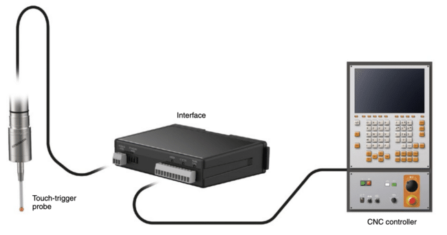
Illustration of Wires Signal Transmission (source)
Probe Calibration in CNC Machines
To guarantee the expected high-accuracy measurements, the probing device is calibrated. The probe calibration process adjusts for inherent characteristics within the measurement system that could cause inaccuracies. The calibration considers characteristics such as the stylus ball’s offset from the spindle center line, its radius, the length of the probe, and the pre-travel.
There are multiple probe calibration methods, which are applied based on the type of probe. One of the most common methods for calibrating measurement touch trigger probes (work probes) uses a test rod and a master ring gauge to establish the offsets in the X, Y, and Z axes. On the other hand, tool probe calibration involves the use of a calibration bar, which is mounted into the spindle. That said, you do not have to master the various calibration methods, as CNC machine and probe device manufacturers usually provide step-by-step guides.
When are Probes Used in CNC Machining?
Probes can be used before, during, and after CNC machining. Some of the activities that require the use of a probe before machining can start include:
- Tool setting, which establishes the length of the tool and its diameter
- Part setting to establish the position of the datum, orientation of the part relative to the CNC machine axes, and component or billet size to determine the stock characteristics
Moreover, you can also use probes to undertake the following operations during machining:
- Breakage detection
- Tool wear detection
- Test cutting tools for wear and deflection to autoload offsets
- Test parts for distortion due to thermal effects
- Inspect parts’ dimensions to ascertain adherence to defined tolerances
Lastly, once the machining has been completed, you can use probes to check the finished parts against their specifications. This allows you to generate reports documenting component conformance.
Types of Probes in CNC Machining
There are six types of probes used in CNC machines:
- Job contact probes
- Touch trigger probes
- Hard probes
- Analog scanning probes
- Laser probes
- Camera/Vision Probes
Hard Probes
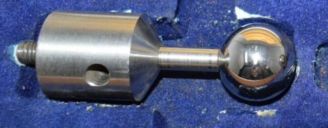
Hard Probe (source)
A hard probe is made up of a solid sphere of known diameter connected to a solid steel shank. To use the probe, an operator manually brings the sphere into tangency with the workpiece and allows the machine to settle. Next, they manually signal the machine to record the probe’s position. The machine’s software then takes over, automatically adjusting the readings to account for the actual diameter of the probe.
For example, if you are using a hard probe to read the diameter of a hole, the software will compensate for the diameter of the probe to display the actual diameter of the hole. However, these probes are primarily used to swiftly locate holes.
Hard probes are not connected to the control unit, meaning they do not relay any information to the machine. This drawback severely limits the latitude of their use. Hard probes can only be used on manually controlled machines; they cannot be used in CNC machines that run automatically.
At the same time, this type of probe is susceptible to human errors. This is because they are wholly controlled by human operators who dictate their approach speed and bounce back. If the operator is not experienced or skilled enough, then they can introduce inaccuracies. And even if they are experienced and skilled, they can still make mistakes. These factors limit hard probes’ usefulness and accuracy.
Job Contact Probes

Job Contact Probe (source)
A job contact probe can only be used with electrically conductive materials. The probe is fitted with light-emitting diodes (LEDs) and is powered by batteries. When the tip of the probe’s stylus makes contact with the surface of the material, an electrical circuit is completed. The LEDs light up, indicating that the stylus has touched the surface of the workpiece. Job contact probes are mainly used as visual indicators of contact during workpiece setup and inspection.
Touch Trigger Probes
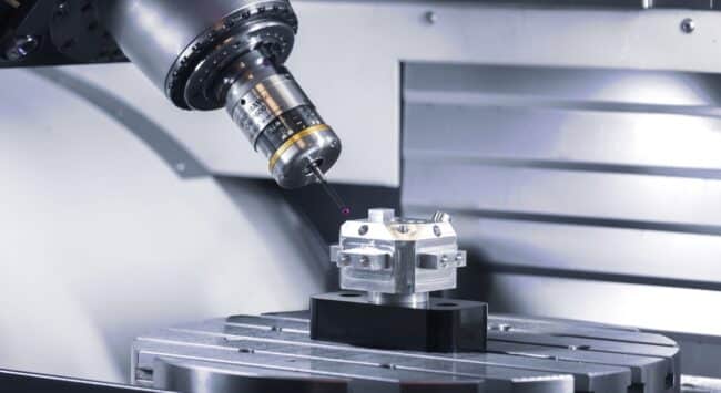
Touch Trigger Probe (source)
Touch trigger probes are the most common type of probes in CNC machines. They are more technically advanced than job contact probes. And unlike the latter type, whose use is confined to electrically conductive materials, the former (touch trigger probes) can be used on any material, provided it is hard enough to cause the stylus to deflect upon contact.
A touch trigger probe has a spherical tip, made from ruby or another suitable material, attached to an omnidirectional joystick/stylus. Thanks to this omnidirectional property, the stylus can deflect in every direction, including inwards.
The touch trigger probe, which is directly connected to the CNC machine’s control unit, works as follows: when the stylus deflects, it changes the electrical characteristics of the circuit, triggering a signal that is sent to the control unit. However, it is worth pointing out that for the stylus to trigger the signal, it must deflect beyond a minimum dimension. This minimum dimension depends on the length of the stylus.
Whenever the control unit receives the signal, it switches off the power to the drive motor, in effect stopping the movement that initially caused the deflection. It is, however, essential to note that touch trigger probes do not measure. Instead, they provide the CNC machines with touch capabilities, enabling the accurate and consistent detection of surfaces or edges. Moreover, the probe does not provide positional information. This role is reserved for transducers.
Touch trigger probes are either table-mounted or spindle-mounted. Table-mounted probes are stationary and are used to check the tools. On the other hand, spindle-mounted probes move to make contact with the workpieces and are used to check and inspect the workpiece.
Analog Scanning Probes
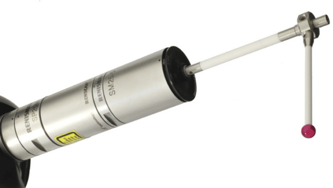
Analog Scanning Probe (source)
A scanning probe typically comprises a scanning module, which houses sensors, and an affixed stylus. The module can carry styluses with lengths from 20 to 400 mm. Depending on your chosen stylus, you can even scan the internal surfaces of features deep inside bores. Scanning probes can collect data from several hundred surface points per second, enabling them to measure the size, position, and form of the part. At the same time, they can acquire data from discrete points, similar to how touch trigger probes work.
Analog scanning probes are preferred when the workpiece comprises irregular or complex surfaces. This is because the stylus tip is brought into contact with the part or feature and then moved along the surface, collecting data during motion. Moreover, the stylus length
Laser Probes
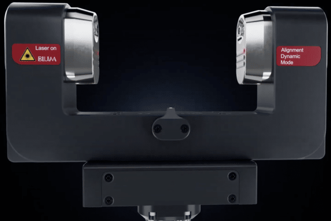
Laser Probe (source)
Laser probes are permanently fixed at a specific distance from the machining area. They are primarily used for tool monitoring and tool measurement. Laser probes are U-shaped, with one arm equipped with a laser emitter and the other a lens that serves as a laser receiver.
To measure the length and dimensions of the tool as well as to monitor its characteristics during machining, the tool is moved to the opening in between the receiver and emitter. The tool activates the probe whenever it blocks the emitted laser from reaching the receiver.
Laser probes measure the geometric characteristics of tools by comparing their measured positions with the measurements of the reference gauge. This gauge, whose length and dimensions are known, calibrates the laser probe during the setup.
Camera/Vision Probes
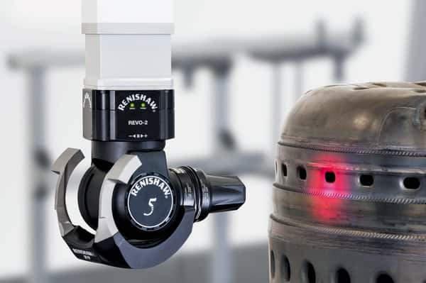
Vision Probe (source)
Vision probes do not directly measure features or parts. Instead, they take a picture of a section of the part, effectively digitizing it and generating multiple measurement points. The probe then uses a database of pictures of electronic models of known dimensions to measure the features of the just-taken image. It achieves this by counting the number of pixels between the measurement points.
This type of probe is mainly used in inspection jobs, particularly in projects where the workpiece is changed frequently. However, the vision probe’s field of view limits the minimum size of features or holes they can inspect. The larger the maximum field of view, the larger the size of the features or holes should be, and vice versa. Vision probes are used to inspect laser-drilled holes or thin sheet metal parts.
Applications of Probing in CNC Machining
Probing systems in CNC machines are used to:
- Measure tool length offset, which lets the CNC machine know how far each tool extends from the spindle to the tip
- Set the Z-axis coordinate
- Identify and set up parts that have been automatically loaded onto a CNC machine
- Measure the dimensional characteristics of features
- Monitor workpiece surface condition
- Inspect and verify the dimensions of finished components
- Identify and measure geometric errors in machine tools, thus verifying tool performance and machine health prior to machining operations
- Detect inaccuracies induced by the control unit or servo drive motors
- In-process gauging, which is the process of measuring a part as it is being machined, allows for adjustments caused by out-of-tolerance tools
- Scanning the form of prototypes to create a raster image file that can be converted to vector formats using software like Scan2CAD
- Tool setting: Tool setting probes are normally table-mounted. They measure the length and size/radius of the tools before cutting commences and check for tool breakage, damage, or wear during the machining operation (by referencing the tools’ dimensional characteristics recorded before cutting started). If the probe detects tool wear, damage, or breakage, it will send a signal to the control unit, whose software alerts the machine.
- Monitor or test cutting tools to autoload offsets
Advantages of Probing in CNC Machining
Probes and probing in CNC machines are advantageous in a myriad of ways, including:
- On-machine part inspection enables part re-working without having to reposition the workpiece
- Probes facilitate efficient production through proper part positioning
- The method of measuring the tool length offset using tool presetting probes is faster, safer, and more accurate than other measurement methods such as part datum or a 1-2-3 block
- Probes eliminate manual part and tool setting errors
- Probing devices reduce with the reliance on fixtures
- They boost productivity by automating tasks that were previously manual, thereby reducing non-productive manufacturing time
- Probing in CNC machines ensures that all parts are correctly machined by enabling the controller to compensate for misaligned parts
- It reduces off-machine inspection requirements
- Probing reduces scrap associated with differences in the sizes of the stock billets
Challenges and Solutions in Probing
The challenges of probing in CNC machining are:
- Probes are expensive
- They can break easily when driven into the workpiece
- Probes can be a source of errors if not calibrated or if mounted incorrectly
Fortunately, you can easily avoid or solve these problems. For one, you can and should follow the manufacturer’s guidelines on how to set up and calibrate the probes. Secondly, you can generate probing programs using dedicated software. Such software is ideal for both experienced and inexperienced G-code programming professionals. It provides a GUI and menus that ease the process of customizing the probing job based on your needs. The visual aid that probing software provides eliminates the guesswork, especially among inexperienced personnel. Moreover, by simulating the probing work, the software lets you visually identify errors that may lead to breakage. It’s equally important to choose the right probe for the task.
Conclusion
Probing in CNC machines enhances automation by streamlining the measurement and inspection processes of manufacturing. This eliminates bottlenecks that otherwise exist if the parts, features, and tools are measured and inspected manually using conventional tools. Probing, however, is more than just inspection and measurement. It encompasses the creation of probing programs, choosing the right type of probe based on the probing technique, probe calibration, and signal transmission.
However, by following manufacturers’ guidelines, you can enjoy the numerous benefits of probes and probing in CNC machines. The advantages include a reduction in non-productive manufacturing time, elimination of manual part and tool setting errors, reduction in scrap and off-machine inspection requirements, and much more. You will also get to use probes in a myriad of ways, from tool setting and tool monitoring to in-process gauging, monitoring workpiece conditions and characteristics, and more.
