If you are an architect, mechanical engineer, or robotics/mechatronics engineer, you may need to learn FreeCAD 3D computer-aided design (CAD) modeling program. FreeCAD is one of the most commonly used CAD software used in architectural & BIM, designing mechanical engineering parts, and robot simulations and it is supported by Linux, Windows, Mac OS, and ChromeOS. (According to FreeCAD, Chromebooks, which run ChromeOS, can support Linux versions of the application.)
To help you start with using FreeCAD, Scan2CAD has compiled a comprehensive guide to help you learn FreeCAD basics in just 1 hour. After going through this guide, you should be able to perform most of the basic tasks in the various FreeCAD workbenches. In this guide, we shall mainly use FreeCAD 0.21.1 (although FreeCAD 0.18 shall also feature severally).

Table of Contents
FreeCAD Download, Installation and Setup
How to Download FreeCAD
To download FreeCAD, follow the steps below:
- Visit the organization’s website (FreeCAD.org)
- Click on the Download tab to open the webpage containing the FreeCAD download files
- Download the file by clicking on the download file that corresponds to your computer’s operating system (as mentioned, FreeCAD is available on Windows, macOS, and Linux)
The process of downloading FreeCAD is similar across the various operating systems. This is because the steps above download the FreeCAD installer or package, which is the file that contains the software. (However, Linux lets you download the software from the official repo.)
How to Install and Setup FreeCAD
While the process of downloading the software is similar for all operating systems, the installation process varies. This section will discuss how to install and set up FreeCAD on Windows, macOS, and Ubuntu Linux.
FreeCAD Installation and Setup on Windows
Once you have downloaded the FreeCAD installer for Windows, a .exe file, double-click on the file to launch the setup wizard. The wizard guides you through the installation of FreeCAD. The wizard lets you read through the license, choose the users for whom you want to install the software, choose the install location, and select the components you want to install alongside the software.
FreeCAD Installation and Setup on macOS
To install FreeCAD on macOS, open the .dmg package with the DiskImageMounter program. Then, drag and drop the software’s icon from the .dmg package into your applications folder. Alternatively, you can use a package manager like HomeBrew. Homebrew is meant to simply the installation of software on macOS. However, you must first download and install HomeBrew, which unnecessarily lengthens the installation process.
FreeCAD Installation and Setup on Ubuntu Linux
FreeCAD makes available the new releases of its software via AppImage packages. However, unlike .exe and .dmg files, AppImage files do not install the software and subsequently add it to your program files/applications folder. Instead, you have to make the AppImage file executable by checking the Allow executing file as program box on the Properties window. Alternatively, you can use terminal commands to make the file executable. With this property now set, you can launch FreeCAD by double-clicking its AppImage file.

Ubuntu Linux Permission Window (source)
Do note that there are other ways to download and install FreeCAD on Ubuntu Linux. For instance, you can download and install FreeCAD from the official Ubuntu repositories via the terminal. With this approach, the operating system resolves all dependencies and installs the necessary files.
Setting Preferences
FreeCAD lets you set preferences for how you want the software to work. Essentially, this feature allows you to customize various settings on the software. FreeCAD then applies those changes permanently – unless you reset them – in what ensures that the software automatically loads your preferred settings every time you open FreeCAD. This way, you do not have to make the changes every time you open the software.
To set your preferred settings, you have to open the Preferences window shown below. You can achieve this by clicking the FreeCAD menu (next to the Apple menu) on the menu bar > selecting Preferences on macOS or the Edit button > Preferences on Ubuntu Linux or Windows.

Preferences Window in FreeCAD
The Preferences window has various sections/panes, each with its own button. These sections combine related settings, simplifying the process of setting preferences. They include:
- General: It includes several tabs – General, Document, Selection, Cache, Notification Area, and Report View. Under these subsections, you can set the size of the toolbar icon, unit system, and number format, choose your preferred theme (preference pack), set the document save compression level, frequency with which FreeCAD should save AutoRecovery files, and the maximum number of files to keep when resaving documents, just to mention a few.
- Display: This section enables you to set display-related preferences like colors, the appearance of the navigation cube, and such rendering options as toggling anti-aliasing on or off and choosing the rendering type (whether perspective or orthogonal rendering).
- Workbenches: It lets you choose the workbenches you want FreeCAD to automatically load when starting up.
- Python: This section includes settings for the Python macro and Python scripting. Python macros let you use Python to perform simple or complex actions in FreeCAD that are not available in the base FreeCAD system.
- Import-Export: The Import-Export section includes settings that affect how files are imported and exported.
- Addon Manager: It lets you install additional workbenches.
- Start: The start section enables you to choose the start page options, e.g., the font type and size, link color, page text color, background color, and more. You also get to choose the workbench you want FreeCAD to automatically switch to after loading.
- Part Design: This section lets you customize the part design options, such as the shape view and shape appearance
- Sketcher: This section lets you customize the sketcher options like the colors of constraint symbols, dimensional constraints, and grid auto-spacing, just to mention a few.
Working with FreeCAD
Orientation
After installing the FreeCAD software, you shall need to understand the FreeCAD interface before starting to draw or model. That way, you shall know where to get the specific tools for performing certain tasks or where to look for certain things as you draw/model.
At the start, the interface may seem complicated, but with the help of this guide, we hope you shall be able to grasp most of the basic features of the interface. With practice, the features shall stick and you shall find it easier with time.
If you are familiar with other CAD software, you shall realize that the main buttons of ‘File’, ‘Edit’, ‘View’, ‘Tools’, ‘Windows’, and ‘Help’ will be found where you expect them to be. The only new button is probably the ‘Macro’ button, which we shall look at later in this guide.
When you open FreeCAD, you will be presented with the FreeCAD start center that looks like the screenshot below. The start center is a welcome screen and it has three tabs namely document, help, and activity.

FreeCAD 0.21.1 Start Center
Starting a New Project
There are several ways to create or start a new project on FreeCAD. These include:
- Using the FreeCAD keyboard shortcut CTRL+N
- Click the File button on the menu at the top of the window and select New
- Click the Create New button on the start page, which opens a new file
Upon starting a new project, the FreeCAD interface changes to the one shown in the image below. We shall start by identifying the various features of this FreeCAD interface.

Main Features of FreeCAD 0.21.1
The most important features to take note of include:
- The Standard Menu that contains the 8 buttons of ‘File’, ‘Edit’, ‘View’, ‘Tools’, ‘Macro’, ‘Sketch’, ‘Windows’, and ‘Help’
- The Workbench Selector
- The Toolbar
- Combo View area that include the tree view under model and tasks view
- Main View area
- The Navigation Cube
You can also add certain features, such as the Report View and Python Console, to the main window. To do this click View > Panels, then toggle on the Report View or Python Console.
FreeCAD Workbenches
FreeCAD groups toolbar buttons, menus, and other interface controls that are specific for certain specialties into different sets called workbenches. If you want to do some architectural modeling, you should use the ‘Arch’ workbench while if you want to draw and model some mechanical parts you can use the ‘Part’ workbench.

FreeCAD 0.21.1 Workbenches
You can look at it as one workshop that has separate workbenches (tables) with specific tools for different specialists.
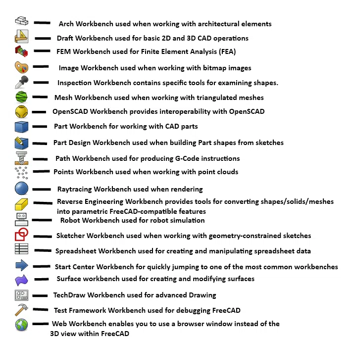
FreeCAD workbenches
In this guide, we shall start with the ‘Part’ and ‘Part Design’ workbenches which are the most commonly used for designing components.
Building a 3D Object in FreeCAD
To build a 3D object, you would need to use the Sketcher and Part Design Workbenches.
We shall start by using the Sketcher workbench to draw a 2D part. For this guide, we shall draw a square. We shall set the size of the sides by defining the length constraints.
We shall then open the Part Design workbench and use the 2D sketch drawn using the Sketcher workbench. The steps followed as below:
- Go to the workbench selector and scroll down to the sketcher workbench and click on it
- Choose the sketch orientation plane you want to use, either XY, XZ, or YZ.
- Choose if you want an inverted orientation, and an offset from the base plane.
- For this guide, we shall use the default plane and options.
- Click OK and start constructing your sketch.
- In the toolbar, select the square

- Move your cursor towards the origin of the sketch, when the coincident constraint
 icon appears, click and move your cursor to draw your square. You can edit the dimensions of the sides of the square to the desired length in the task panel.
 - Press ESC on the keyboard to exit the selected square tool.
- Press the ‘Close’ button, the

- Then go to the workbench selector and select Part Design workbench.
- Select the sketch in the tree view and press ‘PartDesign Body’.
- Select XY-plane and press ‘OK’.
- Highlight the sketch and press ‘Pad’

- Set your desired length and direction in the task panel under the pad parameters.
- Click OK.


When completed, you should have a solid box similar to the one shown below:
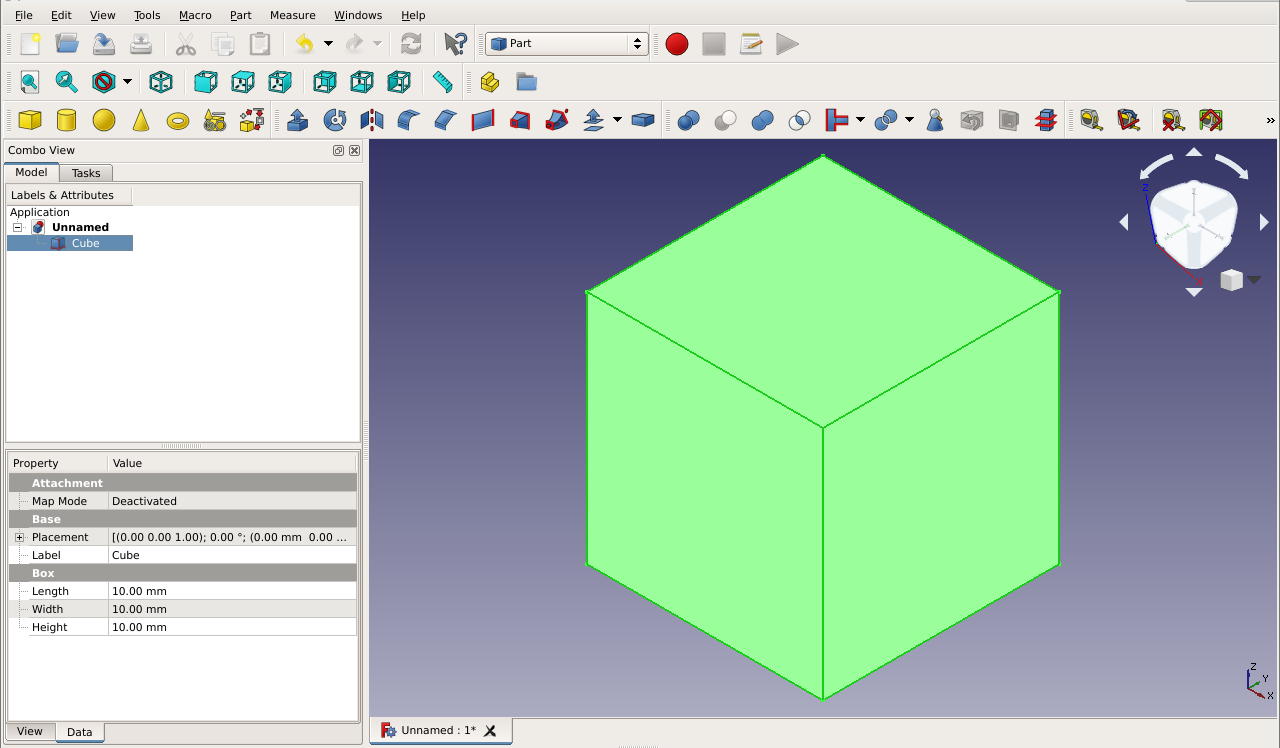
Properties of the box visible in the property section
You can see the properties of the box in the properties section.
After following through this example, you must have come across a variety of tools in the Sketcher and Part Design workbenches. Most of these tools do not require an explanation as to what they are used for since they have shapes suggestive of their work and when highlighted will display their name and a brief description of what they do. You could try drawing any other part using other tools.
Parametric Modeling in FreeCAD
Parametric modeling is a design paradigm that uses relations between dimensions across and within parts to define the geometry of features that make up the parts. Being relational, this design paradigm somewhat simplifies the creation of large projects. This is because by manually altering one or more dimension values, the software automatically adjusts all the dimensions that have relations to those altered values. As a result, the software automatically modifies the geometry of the entire model.
FreeCAD Model Tree
FreeCAD supports parametric modeling in a number of ways. First, it features a tree view in the Model tab. Also known as the model tree, the tree view is, by and large, a history tree that shows all the sequences and steps involved in creating features. It also captures all the changes and relations made by the user and stores data associated with any modifications to the geometry.
To better illustrate the role of the tree view in parametric modeling, let us consider a model created in five steps. FreeCAD names these steps according to the tool used. For instance, if you have created a sketch, then that step will be named Sketch. If you use the Pad command, then that step will be named Pad. (You can rename the steps to better reflect what you are creating.)
Given that the steps are anchored parametric relationships, you can always go back to step 1 to modify the sketch, for example, even when you have reached step 5. And the changes you will make to the objects by going back to step 1 will automatically reflect in the model at all stages of the modeling process.
FreeCAD Spreadsheet Workbench
Secondly, FreeCAD has a Spreadsheet workbench. This workbench allows you to create and edit spreadsheets, populating the sheets with data such as the dimensions of the model. You can then use these data as parameters in the model. This means you do not have to define the dimensions while creating the model. Instead, you can populate the spreadsheet with the dimensions. Then, using the mathematical expression editor, you can create relationships between the model and the values in the spreadsheet.
Saving Files in FreeCAD
You can choose to assign a name for your newly created FreeCAD file by clicking File > Save As or hitting the CTRL+S keyboard shortcut. Next, type out a name, choose the folder you want the file to be saved, and, finally, click Save. By default, FreeCAD saves the files using the FCStd file format.
Exporting Files in FreeCAD
To save the files using other supported file formats on FreeCAD – such as DXF, DWG, IDES, STEP, STL, SVG, VRML, and more – you have to use the Export command. Wondering how to export files in FreeCAD? The process is quite simple; it involves the following steps:
- Select all the solids you want to export. You can achieve this by manually selecting the objects or using the CTRL+A keyboard shortcut
- Click the File button and select Export or use the CTRL+E keyboard shortcut
- Choose the file format to which you want to export your project
- Click Save
Importing Files into FreeCAD
To import files into FreeCAD, follow the steps below:
- Create a new FreeCAD project
- Switch to the workbench that best represents the model you want to import
- Click the File button and select Import or use the CTRL+I keyboard shortcut
- In the file explorer window, navigate to the location of the file you want to import and double-click on that file to import it
If you have imported mesh formats like STL/OBJ, which are dimensionless, scale the model after converting it to a solid. You can also scale the model in the application it was created with prior to exporting it. Scaling is essential because FreeCAD assumes that the units used in the model are millimeters.
Common Tools in Various FreeCAD Workbenches and Their Function
Sketcher workbench
|
Tool |
Description |
| Point | Drawing a point |
| Line by 2 points | Drawing a line by joining two points |
| Arc | Drawing an arc using the center, radius, start angle and end angle |
| Arc by 3 points | Uses two endpoints and another point on the circumference to draw an arc |
| Circle | Drawing a circle using center and radius |
| Circle by 3 points | Draws circle using three points on the circumference |
| Rectangle | Drawing rectangle using two opposite points |
| Triangle | Drawing a regular triangle |
| Square | Draws a regular Square |
| Hexagon | Draws a regular hexagon |
| Pentagon | Draws a regular pentagon |
| Trim | Trims a line, arc, or circle with respect to a clicked point |
| Construction Mode | Toggles an element to/from construction mode where an object will not be used in a 3D geometry operation and it is only visible while editing the sketch that contains it |
| Mirror | Mirrors selected elements of a sketch |
| Merge | Merges sketches |
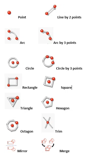
Sketcher workbench commonly used tools
Part Design Workbench
|
Tool |
Description |
| Pad | Extrudes a solid part from a sketch |
| Revolution | Revolves a sketch about an axis to produce a solid part |
| Chamfer | Chamfers the edges |
| Created a pocket from a selected sketch that is mapped to an existing solid part | |
| Groove | Revolves a sketch around an axis to generate a groove |
| Fillet | Rounds or creates fillets on the edges of an object |
| Mirrored | Mirrors objects on a face or plane |
| Linear pattern | Replicates parts in a linear pattern |
| Polar Pattern | Replicates parts in a circular/polar pattern |
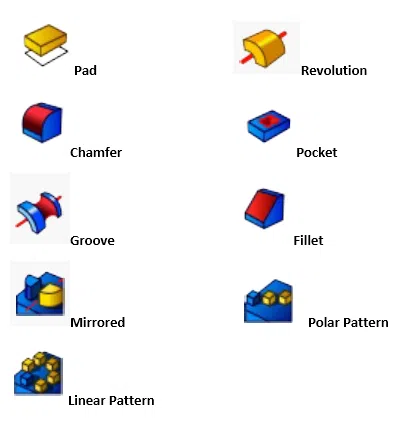
Part Design workbench commonly used tools
You can also select create a new sketch in Part Design workbench to access all the tools from Sketcher workbench. The Part workbench contains tools that are similar to those in the Part Design workbench.
With practice, you will get acquainted with more advanced tools from the workbenches you frequently use.
Navigating in the 3D view
Once you build your 3D object, you will need to move it around or rotate it to work on specific features or sides/faces.
To do so, you will need to first understand the FreeCAD 3D view space, which is a Euclidean space, meaning it has an origin point and three axes namely X, Y, and Z.

Euclidean space axes
To navigate in the 3D view, you can choose to use the mouse, keyboard shortcuts, or the Navigation Cluster.
You can Pan, Rotate or Zoom and even select different objects or screens using the different FreeCAD navigation modes that are accessed from the Preferences screen or by right-clicking on the 3D view area.
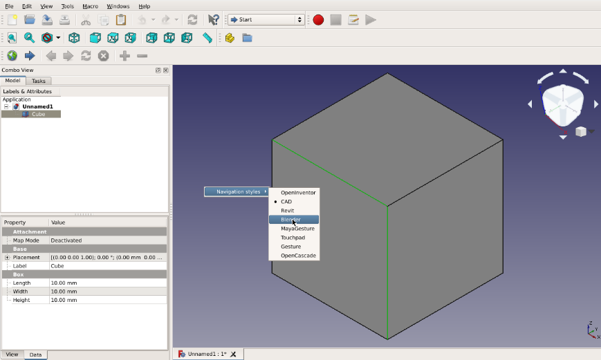
FreeCAD navigation styles
The navigation styles in FreeCAD include OpenInventor, CAD, Revit, Blender, MayaGesture, Touchpad, Gesture, and OpenCascade.
Navigating using the Mouse
To use the mouse to navigate, right-click on the 3D view area and select the navigation style you want, and use the operations outlined in the screenshot below for the different navigations modes
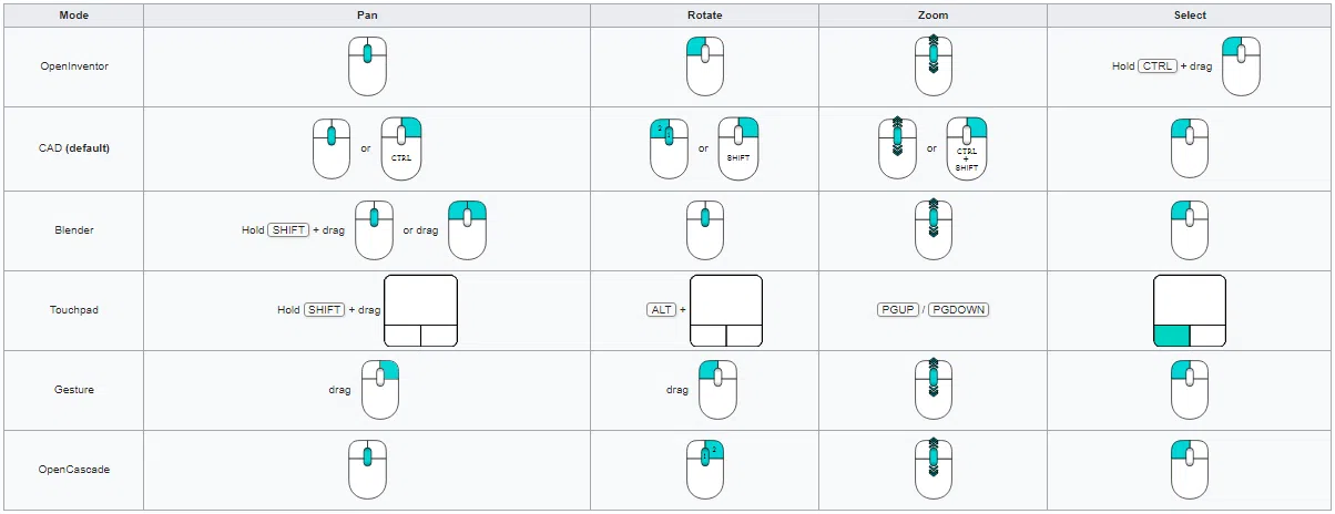
Mouse navigation in FreeCAD (source)
Navigating using keyboard shortcuts
| CRTL + ‘+’ | Zoom In |
| CRTL + ‘-‘ | Zoom Out |
| Arrows | To view left, right, up, and down |
| SHIFT + Left arrow | Rotate 90 degrees to the left |
| SHIFT + Right arrow | Rotate 90 degrees to the right |
| 0,1,2,3,4,5,6 | For Isometric, Front, Top, Right, Rear, Bottom and Left respectively |
| VO (held at the same time) | Orthographic view |
| VP (held at the same time) | Perspective view |
| CTRL and right-click on parts/features | Selecting more than one feature/parts |
View the full list of FreeCAD keyboard shortcuts.
Navigating using the Navigator Cluster
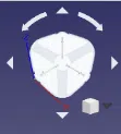
FreeCAD navigator cluster
This can be used to rotate the object around. When the mouse hovers about a certain point on the navigator cluster, it turns blue. If it is the side you want to see or use to rotate click it and hold and move in the direction you want to rotate or simply click if it a face you want to view.
Basic Troubleshooting
1. FreeCAD Freezes or Crashes during Operation
FreeCAD is known to freeze, with many a user reporting online the circumstances under which the software froze. The software can freeze for several reasons, including incorrect usage of the workbenches and tools, snap-related issues (on Ubuntu), graphics driver-related issues, OS-specific issues, and more. Given the varied nature of these reasons, there is a compilation of OS-specific issues on the FreeCAD forum, complete with workarounds. If you cannot fix the issue using the recommendations therein, consider posting your issue on the forum.
2. FreeCAD Cannot Open or Save CAD files
In cases where you encounter errors when writing files to network devices or your computer does not use the .FCStd file extension on saving (in Ubuntu), open the Parameter editor, navigate to BaseApp/Preferences/Dialog, and create a Boolean parameter called DontUseNativeDialog and set it to true.
If you are using ChromeOS, ensure you have turned off GPU acceleration. Failure to disable this option presents the following problem: FreeCAD will stop responding when it tries to create or open a file. FreeCAD may also fail to start or open files if it is running on hybrid systems (computers that use two distinct GPUs). In such a case, you may need to change the driver settings.
3. Objects Are not Visible in the 3D view
Whenever you create a new sketch for a part or body, FreeCAD automatically hides the object. A hidden object is displayed on the model tree as a grayed-out icon. To make it visible, click on the object you want to make visible and tap the space bar. This action toggles between visible and invisible. If the object, which can be a part that makes up a body, is still not visible when you hit the space bar, that could be due to the fact that the body is not visible. To solve this issue, click on the body and press the space bar.
4. Trouble Installing or Updating FreeCAD
If you are having trouble installing or updating FreeCAD, consider alternative installation methods. If on macOS, try using HomeBrew. If on Ubuntu Linux, use the sudo apt command.
Sometimes, on Windows, you may encounter system errors that prevent the installation of FreeCAD. If you encounter a system error such as “The code execution cannot proceed because MSVCP140_1.dll was not found,” for instance, reinstall the missing file to fix the problem.
5. Error Message When Trying to Perform a Task
If FreeCAD presents an error message, simply search online for its meaning. In the event that there are no writeups on the problem, post a question on the FreeCAD forum. This approach is the most feasible, given that you could encounter plenty of error messages.
Practice Exercises
YouTube is home to numerous practice exercises and tutorials for new – and seasoned – users of FreeCAD. Here are several models you can try out to familiarize yourself with the various tools and workbenches:
You can also try out our list of the top 20 CAD 3D models.
Additional Resources and Tutorials
The official website links to a wiki page that contains numerous FreeCAD tutorials. These tutorials discuss how FreeCAD is used in various fields, including architecture and building information modeling (BIM), drafting and sketching, technical drawings, finite element model analysis, CNC and 3D printing, rendering, scripting, and robotics. They also discuss how to create models that are specific to these fields.
You can also check out various creators’ YouTube channels for videos that discuss how to use FreeCAD’s features and tools. One such channel is Joko EngineeringHelp, which has published a comprehensive video titled “Complete Beginners Guide to Part Design.” To access other videos, type “FreeCAD tutorial” on the YouTube search bar. Beyond the video tutorials, you can check out users’ posts on the FreeCAD forum
Conclusion
FreeCAD may seem hard to learn especially due to the many workbenches. But on the contrary, it is one of the CAD software that has a favorable learning curve. With this guide, you can learn FreeCAD basics in just an hour.
