Creating 3D CAD models is a perfect way to discover the ins and outs of any part or assembly. It is also an ideal avenue to learn about – and hone skills in – how to use some of the features of 3D CAD and CAM software. However, sometimes you hit a wall: just what should you create next? How do you go about creating the CAD models? Whether you are a CAD beginner or an old hand, there are always times when you need a little inspiration. Luckily for you, we here at Scan2CAD have just the solution. We have compiled a list of the top 20 3D CAD models you need to try out in SolidWorks and AutoCAD.
There’s something for everyone on this list, ranging from the simplest of parts to the most complex of machines. We have also incorporated the various aspects of 3D modeling, including sketching, sheet metal design, die-casting mold design, working with surfaces, multi-body part design, and working with both parts and assemblies. We have also thrown in links to some handy tutorials that enable you to create these models yourself! Even more conveniently, the creators in some of these tutorials go the extra mile by discussing how to perform simulations and create animations. Read on for the full list and get creating!
Table of Contents
Top 20 3D CAD Models for AutoCAD and SolidWorks
1. Spoon
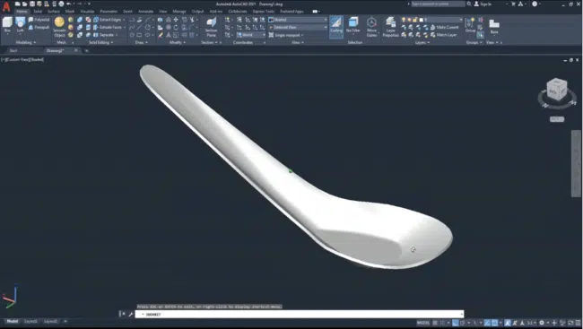
We’ll start things off with a 3D model of a spoon, created using AutoCAD. This model is quite simple. The modeling process involves drawing a few lines and curves and using commands such as mirror, loft (similar to extrude), and move. Depending on your knowledge of the various AutoCAD commands and shortcuts, it can take just a few minutes to complete. And using the knowledge gained from the tutorial, you can try out other spoon designs, including skimmer spoons and serving spoons.
Software: AutoCAD
Interested? Check out the spoon tutorial
Source: Eang Sopheann
2. Mug

Our next 3D model is a mug, created using SolidWorks software. This 3D CAD model is perfect for beginners. It introduces concepts such as sketching and dimensioning on SolidWorks. Moreover, the creation process is markedly different from what you may have encountered when using AutoCAD for 3D modeling. SolidWorks supports parametric modeling, while AutoCAD supports direct modeling. So, creating the 3D CAD model of a mug as a beginner introduces you to parametric modeling. In addition, you can use SolidWorks to conduct simulations and analyses, including a drop test.
Software: SolidWorks
Interested? Check out the mug tutorial
Source: 3D Models
3. Roller Chain
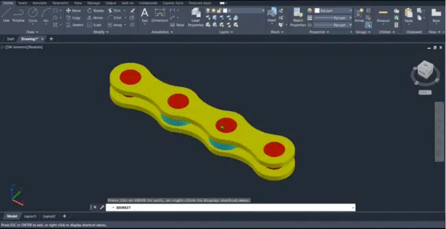
If you have ridden a motorcycle or bicycle, then you are familiar with the roller chain. And although its design can be quite complicated, the tutorial below takes a more simplistic approach. Based on this approach, the 3D CAD model of a roller chain is ideal for beginners looking to understand how to create 3D models using AutoCAD. (You will notice that the creator is working within and using tools from AutoCAD’s 2D environment. This means you can create 3D CAD models within AutoCAD’s 2D environment.)
Software: AutoCAD
Interested? Check out the roller chain tutorial
Source: TechTutorials
4. Hammer
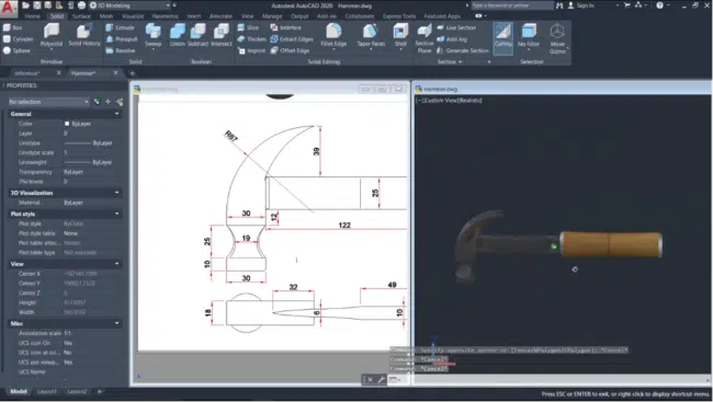
Tools are as essential within the CAD environment as in the real world. And what better way to merge the two realities than to use AutoCAD tools to design a real-world tool, a hammer? The tutorial below will show you how to create this model with various AutoCAD commands, including subtract, loft, presspull, fillet edge, and more. It also explores how to select materials from AutoCAD’s material browser.
Software: AutoCAD
Interested? Check out the hammer tutorial
Source: Classical CAD
5. Plastic Mesh Storage Container
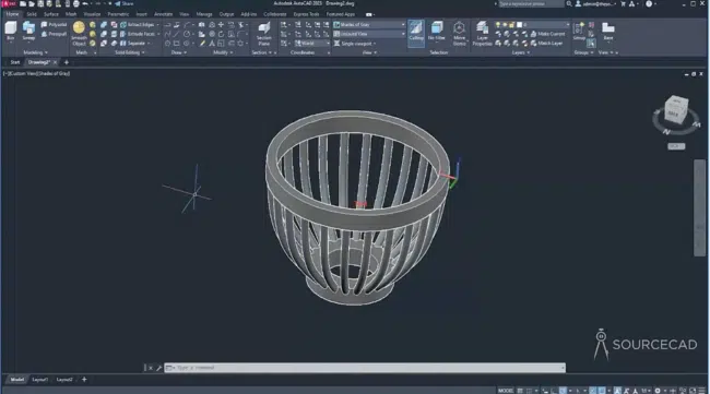
Are you looking for a custom storage container? You may consider creating it yourself from scratch. The process would involve coming up with a 3D CAD model of the design using CAD software like AutoCAD. Next, you will have to convert the CAD file to G-code file formats like .CNC or .NC file using conversion software like Scan2CAD or CAM software. The last step would involve importing the G-code file into a 3D printer, which creates the container.
The tutorial below discusses this process in great detail. The tutorial’s creator uses AutoCAD to design a plastic mesh container. He uses a number of AutoCAD 3D modeling tools like array (polar array), sweep, and union, just to mention a few. We are confident the tutorial has the information you need for simple do-it-yourself (DIY) projects like creating a plastic mesh storage container.
Polar array, union,
Software: AutoCAD
Interested? Check out the plastic mesh storage container tutorial
Source: SourceCAD
6. Screw
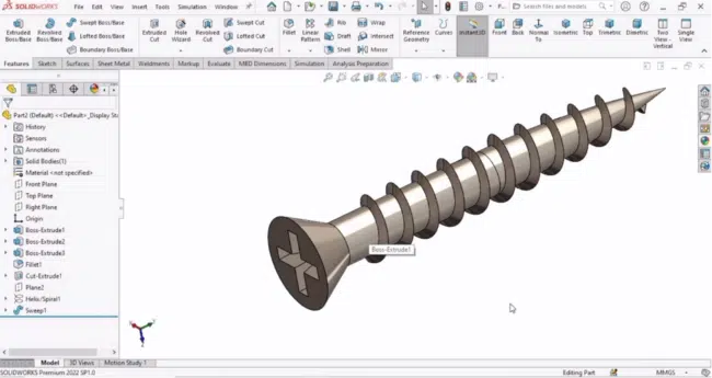
You have probably joined numerous parts using screws, so why not find out exactly how they are designed. SolidWorks makes the process of creating a screw model rather simple, as you will see by watching the tutorial below. It takes you through how to design and model the various parts of a screw: the head, drive, shank, thread, and tip. You will also learn about some SolidWorks commands and tools that you may not encounter while watching the other tutorials on this list. These commands include trim, relations, and draft, just to mention a few.
Software: SolidWorks
Interested? Check out the screw tutorial
Source: Robo CAD
7. Nut and Bolt
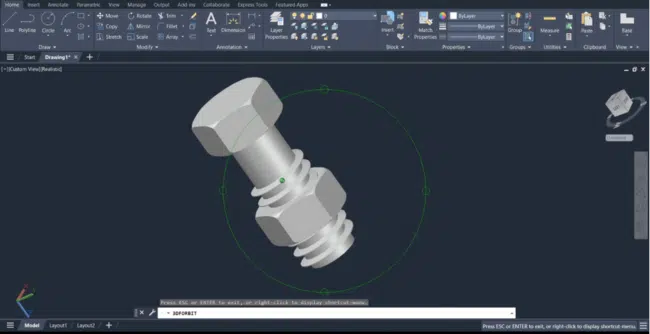
The humble nut and bolt are staples of the mechanics and engineering industries and can be found practically everywhere in the built environment. If you are starting out creating CAD models, why not consider designing a nut and bolt? Using the tutorial below, you will fly through AutoCAD features and tools such as sketch, extrude, sweep, intersect, presspull, move, and more.
Software: AutoCAD
Interested? Check out the nut and bolt tutorial
Source: TechTutorials
8. End Mill Cutter
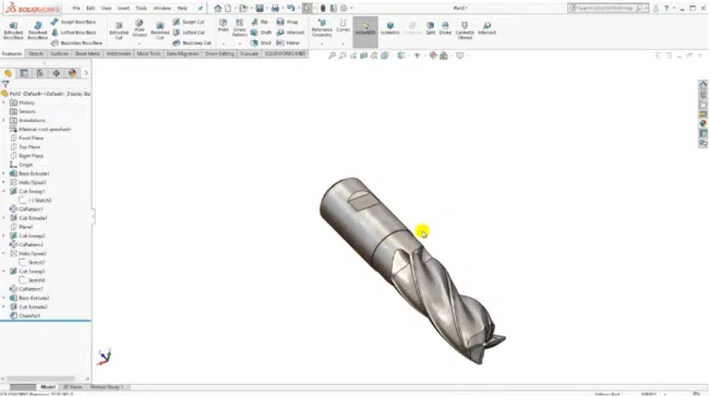
Computer numerical control (CNC) machining tools come in multiple shapes, sizes, and materials. In fact, the need for accuracy in manufacturing has given rise to micro-machining, which utilizes miniaturized tools called micro-tools. But, like the features and parts they help create, the machining tools are also products of the design and manufacturing processes. And if you have ever wondered about the design and modeling of end mill cutters – or any other machining tool – then the tutorial below is an excellent place to get answers.
Software: SolidWorks
Interested? Check out the end mill cutter tutorial
Source: 3D Models
9. Shaft and Ball Bearing Assembly
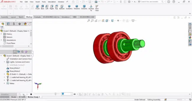
Ball bearings are virtually indispensable in mechanical engineering. They are used in cars, tricycles, bicycles, skateboards, machine tool spindles, and a number of other machines and products that support motion. While the design of a ball bearing does look complicated, SolidWorks simplifies the whole process. It has a design library that comprises many premade models, including the ball bearing. Simply drag the ball bearing from the library to add it to your workspace.
Nonetheless, there is still a lot to learn while working on this project. For instance, you will learn how to design the shaft from scratch and automatically add threads. In addition, you will also learn how to add the bearing and create the shaft-ball bearing assembly. Moreover, the tutorial discusses how to test out the motion feature; it details how to initiate a motion study analysis. Thus, in addition to creating the model, you can see how it would function in real life.
Software: SolidWorks
Interested? Check out the shaft and ball bearing assembly tutorial
Source: Robo CAD
10. Feeding Hopper
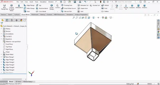
SolidWorks supports sheet metal design. To learn how to create sheet metal designs, consider checking out – and creating the feeder hopper design in – the tutorial below. It covers how to use a number of sheet metal commands, including setting the sheet metal parameters, working with edge flanges, dimensioning, and more. Of course, a feeding hopper is not used in isolation. It is usually part of an assembly. To learn how to create other parts of the assembly, such as a tube frame and the discharge pipe with a built-in screw conveyor, check out this SolidWorks tutorial.
Software: SolidWorks
Interested? Check out the feeding hopper tutorial
Source: RoboCAD
11. Sprinkler Head
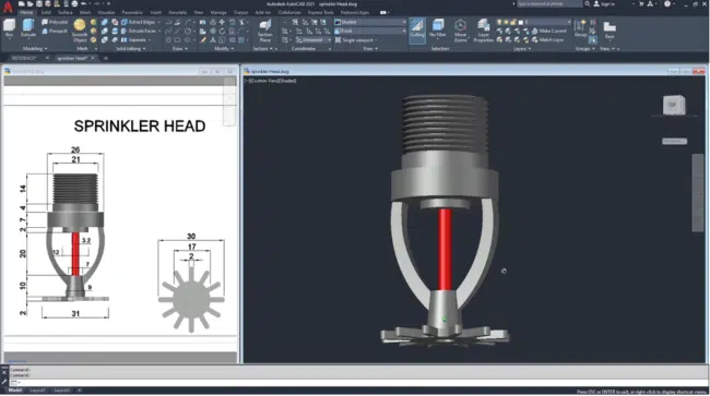
The sprinkler head is perhaps the most visible part of an automatic sprinkler system. And given that certain buildings must have automatic sprinkler systems installed, there is a high likelihood that you have come across a sprinkler head. This 3D CAD model is rather intricate as it is made up of variously shaped components. Its complexity makes for a worthwhile project. The tutorial below goes into how to use AutoCAD to create a 3D model of a sprinkler head.
Software: AutoCAD
Interested? Check out the sprinkler head tutorial
Source: Classical CAD
12. 3D Pipe Fittings and Pipe Assembly
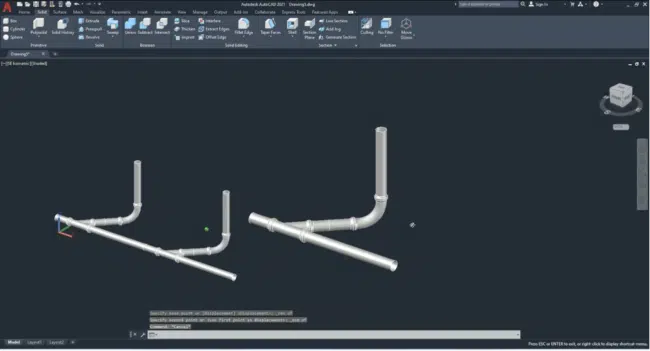
The tutorial below takes on a different design approach: it creates 3D geometry using meshes and dynamic blocks (and 2D wireframes). With this tutorial, you will learn how to create 45° junction pipe and 90° elbow pipe fittings as well as pipe assemblies. It covers non-conventional AutoCAD commands (and system variables) like SURFTAB1, SURFTAB2,RULESURF, SELECTIONCYCLING, BACTIONSET, and many more.
Software: AutoCAD
Interested? Check out the 3D pipe fittings tutorial
Source: SL – Engineering Solution
13. Pipe Support Assembly
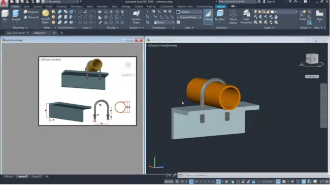
Pipes are not self-supporting; they require external supports that transfer the pipe’s dead weight as well as the loads generated because of the content channeled through the internal cavity to the ground or superstructure. The tutorial below delves into how to design a simple pipe support assembly. It starts with the design of a U-bolt and fastening nuts before detailing how to model a 3D pipe. Then, the tutorial discusses how to design an angle bar. Finally, all these parts are assembled, creating a pipe support assembly.
Software: AutoCAD
Interested? Check out the pipe support tutorial
Source: Classical CAD
14. Water Tap
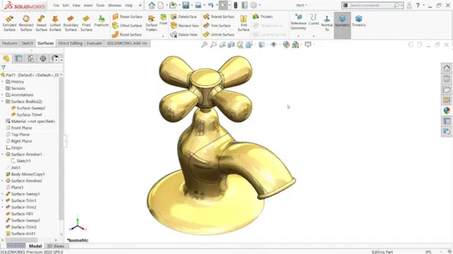
You have probably used a water tap several times today, but have you wondered what goes into creating it? Well, the initial stages of the creation process involve, among others, modeling. Here, designers and engineers come up with designs and 3D models. The designs can involve complex geometry, with the 3D modeling aspect requiring designers to work with surfaces. The tutorial below captures more or less every aspect of the design process, detailing how you can use surface tools such as revolve, sweep, and trim to create a 3D CAD model of a water tap.
Software: SolidWorks
Interested? Check out the water tap tutorial
Source: CAD CAM Tutorial By Mahtabalam
15. Water Tap Die-Casting Mold
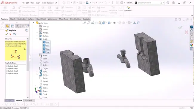
With the water tap design completed and approved, the next step beckons: designing the molds that will then be used to shape the water tap’s internal and external geometries. Typically, the manufacture of water taps requires two different die-casting molds.
The first mold produces solid parts (molds) whose shapes correspond to the internal geometry of water taps. Usually, fine quartz sand is forced into this mold and then baked to create these solid molds. These solid molds are then placed into the second mold that features the external geometry of the tap. Molten metal is then poured into the mold, covering the solid mold emplaced inside the second mold. Both molds, therefore, define the shape of the mold. Finally, upon removal from the second mold, the tap is vibrated to remove the baked sand, creating an internal cavity.
The tutorial below discusses how to create water tap die-casting molds. Put simply, with this tutorial, you will learn mold design in SolidWorks.
Software: SolidWorks
Interested? Check out the water tap die-casting mold tutorial
Source: Engineering School D
16. Piston
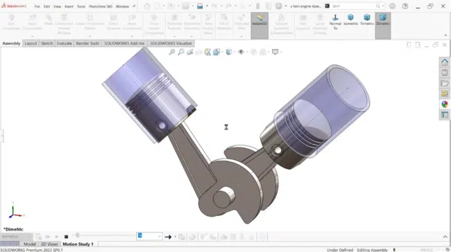
Are you looking for more complex CAD models to create? How about modeling the components of an internal combustion engine? To start things off, we have a piston. The tutorial below covers the design and modeling of connecting rods. It discusses multiple SolidWorks tools and commands. These include extruded-cut, dimensioning, revolve feature, change appearances, dome command, working with planes, and the mirror command, just to mention a few.
Moreover, this tutorial will teach you how to create assemblies, including the various assembly tools. It is a perfect resource if you are just getting started in the world of CAD and 3D modeling or are unfamiliar with assemblies. Lastly, it also teaches the exact commands to activate simulations and animations.
Software: SolidWorks
Interested? Check out the piston tutorial
Source: CAD CAM Tutorial By Mahtabalam
17. Connecting Rod
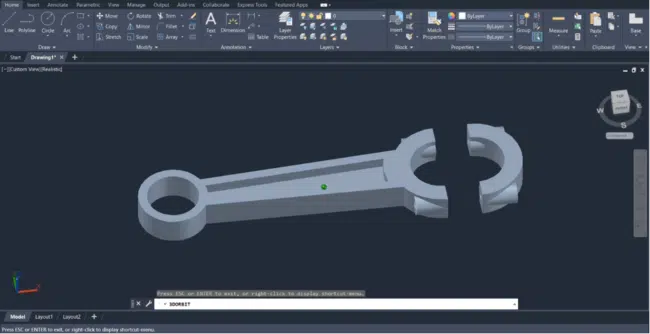
Connecting the piston to the crankshaft is an equally important component of the internal combustion engine: the connecting rod. And while the tutorial above covered how to use SolidWorks to create a piston, you can also incorporate AutoCAD in the design of ICE components. The tutorial below, for example, discusses how to create a 3D CAD design of a connecting rod in AutoCAD.
Software: AutoCAD
Interested? Check out the connecting rod tutorial
Source: TechTutorials
18. Crankshaft
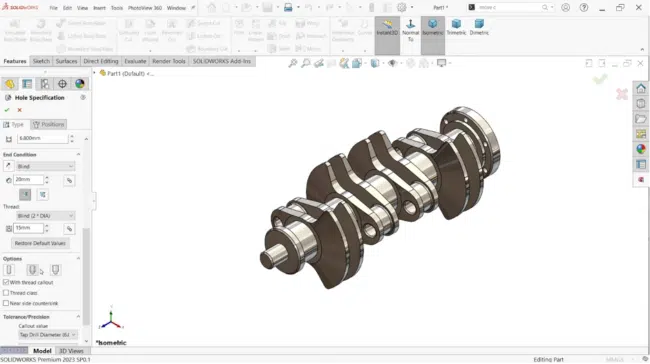
SolidWorks supports multi-part design. As a result, it facilitates more efficient and flexible part design. This modeling approach is used to create models of products that feature several smaller parts. One prime example is a crankshaft. The tutorial below covers how to create a 3D CAD model of a crankshaft. It covers multiple SolidWorks tools, including mirror, rotate, chamfer, fillet, dimensioning, and more. With this tutorial, you will learn how to combine multiple parts, as well as how to apply materials.
Software: SolidWorks
Interested? Check out the crankshaft tutorial
Source: CAD CAM Tutorial By Mahtabalam
19. Shock Absorber
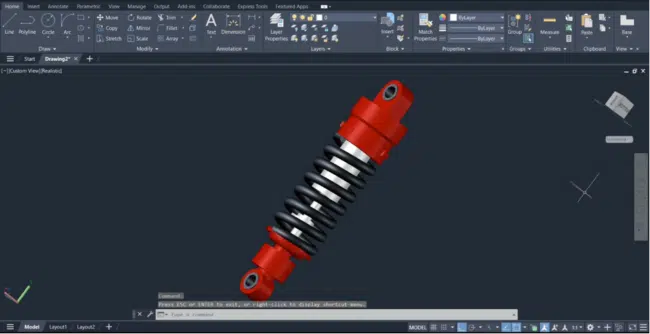
3D CAD models can have complicated geometry. And while there are more advanced 3D modeling software products that are specifically designed to help you create such models, AutoCAD is not one to be left behind. This is despite the fact that this is not one of its strongholds. With AutoCAD, you can create a shock absorber, for example. The tutorial below explores how to use AutoCAD to create 3D models with complicated geometry.
Software: AutoCAD
Interested? Check out the shock absorber tutorial
Source: TechTutorials
20. Mouse
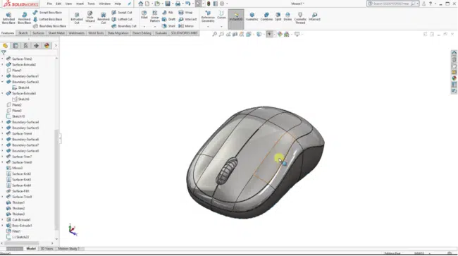
This model is quite challenging. And as a testament to how challenging it really is, the tutorial is more than 1-hour long. This 3D CAD model of a mouse is a particularly worthwhile project because it is centered around surface modeling. (Surfaces are a type of geometry used to create solid features.) By taking on this project, you will learn how to extrude surfaces, work with dimensions, and more.
Software: SolidWorks
Interested? Check out the mouse tutorial
Source: 3D Models
Conclusion
3D CAD modeling involves the creation of various parts with built-in features. The parts are made of different materials and surfaces and have their own distinct and sometimes complicated geometry. To help you create these 3D parts, software like SolidWorks and AutoCAD nonetheless come with numerous 3D modeling tools and features. For instance, SolidWorks has tools that enable you to create sheet metal parts, surfaces, and assemblies. On the other hand, AutoCAD lets you create solid parts using meshes, for example, which is a different 3D modeling approach. Against this backdrop, our list of the top 20 3D CAD models to try out covers all these approaches. It includes an array of models, whose creation falls in different sections of the hardness spectrum; from simple to complicated. As such, the top 20 3D CAD models are perfect for beginners and seasoned CAD users alike.
