The manufacturing and modeling industries are constantly advancing—adapting to new needs and changes in industry standards. The entire market and maker community, however, wouldn’t be anywhere if not for computer aided manufacturing (CAM). CAM has certainly has had an interesting history—spanning back as far as the 1940s. Not familiar with the history of CAM? That’s fine—we’ve got you covered.
Scan2CAD has put together a complete guide covering the beginning of CAM and the first NC machine all the way up to present day.
Table of Contents
Computer-Aided Manufacturing
Computer aided manufacturing (CAM) typically refers to the use of numerical control (NC) software to create G-code to drive computer numerical control (CNC) machine tools for manufacturing parts and products. Essentially, CAM takes information from a computer generated design—or CAD drawing—to create instructions that control the movements of an automated tool. These automated tools can include anything from water jets to mills to plasma cutters.
The primary purpose of CAM is to speed up the production and manufacturing process. It works side-by-side with CAD software so that you can take designs directly from CAD and use CAM to produce them. In most cases, all you need to provide are raw materials and instructions like feed rate, speed and dimension.
The earliest examples of CAM technology lie in NC machines used in the early 1950s. Nowhere near as intuitive or advanced as the machines you’re probably used to nowadays, these machines used coded instructions on punched paper to control simple manufacturing instructions. We’ll take a look at how these simple machines developed into the complex ones we use now—and how CAM evolved in kind.
Timeline Visuals: History of CAM
Throughout the history of CAM, there have been multiple milestones that have driven the evolution of the industry. These milestones have included the founding of CAM software development companies as well as the release of CAM software and technologies.
CAM Companies Founding Dates
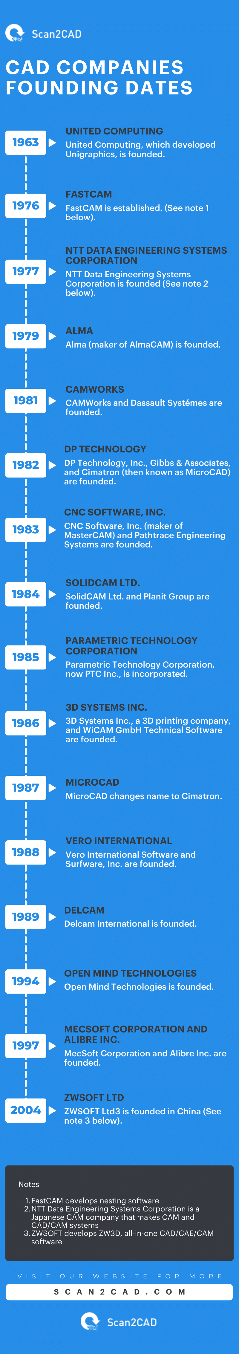
Infographic of CAM Company Founding Dates. Click to view full size.
CAM Software and Technologies Release Dates
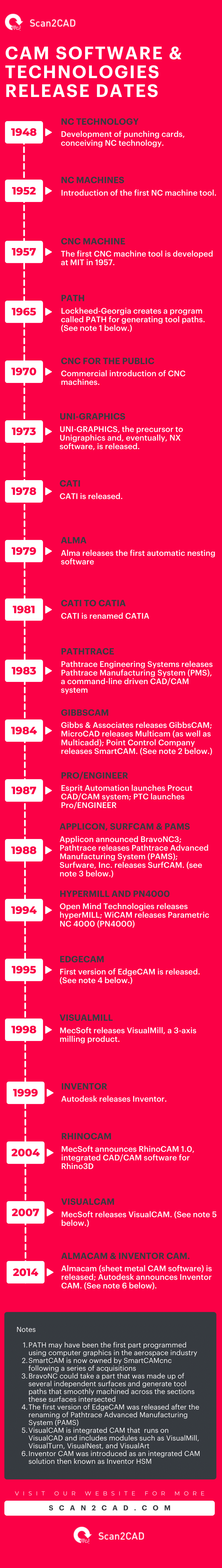
Infographic of CAM Software Systems’ Release Dates. Click to view full size.
Technical Advances in CAM Space
A discussion of the history of CAM is incomplete without mentioning the technological and technical advances that led to its development and evolution. In the pre-1950s era, punched cards were widely used as data-recording media. They laid the foundation for the development of punching tapes, which were subsequently used in the first NC machine, introduced in 1952. Since then, the CAM industry and, by extension, the manufacturing space has witnessed multiple other developments, from the Automatically Programmed Tool (APT) language and post processors to personal computers, CAM systems, and CAD/CAM systems. Here’s more on these technical advances.
Punched Cards
Punched cards were historically used as data-recording media. Card punch devices were used to punch holes into the punched cards. Each hole represented machining instructions, such as the incremental movement of the machine tool. Card readers were then used to transfer part programming data from the punch cards to the computer systems.
Punching Tapes
Punching tapes were advanced as a solution to the shortcomings of punching cards. While cards had limited space, meaning the machinists needed many punching cards to produce even the simplest of parts, tapes had a continuous surface area. Coded symbols in the form of holes were imprinted into the punching tapes using paper tape punchers. These symbols represented the part program. They were then read using punched tape readers, which were designed to sense the presence or absence of holes.

Standardised NC Punching Tape (source)
Punching tapes were utilized in both manual part programming and computer-assisted part programming. In the former scenario, machining instructions were prepared on a part machining manuscript, a form that listed the relative positions of the cutter or workpiece. Next, these instructions were transferred onto the punching tapes using a typewriter-like device that could make the holes.
On the other hand, in computer-assisted part programming, the computer undertook most of the tedious and time-consuming computational work. More specifically, the computer interpreted the machining instructions and performed calculations to convert these instructions into motion commands for the machine tool. It also controlled the tape punch device, which prepared the punching tapes for specific NC machines.
In either case, the part programmers verified the punching tapes for accuracy before using them in production. Nonetheless, preparing these punching control tapes was a time-consuming exercise. By the time the first NC machine tool was introduced, industry players recognized that a more efficient process of producing these tapes was necessary to support the economics of using NC in production. Thus, work began to automate this process, culminating in the development of the Automatically Programmed Tool (APT) language.
NC Machines
The birth of NC is largely credited to John T. Parsons. Working as a machinist for his father’s company, Parsons began to look for ways to build helicopter rotors. In a bid to speed up the production process, Parsons began to look towards the idea of using punched card machines to generate engineering calculations. Working with Frank Sulen, Parsons developed punched cards that could be programmed to provide automated machining. These punched cards didn’t gain much traction, however, until 1949 when the US Air Force arranged funding for Parsons to build his own machine that would surpass the performance of current NC machines.
In order to further develop his machine, Parsons turned to the Servomechanism Laboratory at MIT in 1949. With their help, the first NC prototype was developed. The first NC machine tool was subsequently introduced in 1952. In this time, a system designed to gauge how far controls turn was also developed. The US Air Force stopped its funding in 1953 due to high expense; however, the project was promptly resumed by Giddings and Lewis Machine Tool Co.

Image source: cmsna
A turning point for the first CNC machine was the production of punch tapes under computer control by John Runyon of MIT. With it, the time needed to create instructions and then manufacture the subsequent part was vastly reduced. This success led to the production of many more CNC machines in the following years. Efforts in later years were made to push them into the general manufacturing market.
Automatically Programmed Tool (APT)
Beginning in June 1956, work got underway at MIT’s Servo Lab, eventually leading to the development of an Automatically Programmed Tool (APT). The Computer Applications Group, led by Doug Ross, was responsible for the APT project. And although the project was domiciled at MIT, it involved numerous large industrial companies, particularly in the aerospace industry. Thus, APT was rolled out and was first used in production around 1959. The original version was a two-dimensional implementation. However, further development led to three-dimensional implementation, with the language capable of controlling up to five axes.
For clarity, APT was – and still is – a high-level, general-purpose programming language that defined toolpaths for creating geometries on workpieces. The language was first intended for use as a contouring language but evolved. Moreover, as originally designed, besides being a language, APT was also a computer program that used APT statements to perform calculations in a process that generated the position of the cutter.
APT made NC technology successful by pioneering a method that is still used to date. It introduced a concept whereby NC information was prepared in a generalized format before being converted to a machine-specific form using post-processors. This approach enabled programmers to develop post-processors specific to each machine. Also, it allowed the output from the APT program to be shared among different entities prior to post-processing. APT is still used today chiefly by aerospace companies and large machine shops. It is currently fully supported by Austin NC, Inc.
In its formative years, APT was criticized for being too demanding on existing computer hardware at the time. Still, it was a significant accomplishment; it was a precursor to modern CAM software.
Post Processors
The concept of post-processors emerged during the formative years of APT. And although CAM systems have since replaced the use of APT systems, post-processors are still in use to date. Post processors are separate computer programs that prepare instructions for specific machine tools. They were introduced because APT was designed as a general-purpose language, meaning it was used to write universal instructions that applied to multiple machine tools.
Post processors were originally developed in the mid-1950s, but like CAM or CAD/CAM systems, they have evolved and become more advanced. Early on, post processors were used to prepare punching tapes for specific machine tools. The output of earlier versions of post processors was an NC punching tape prepared in a particular format that can only be read by the machine on which it is used. This principle still guides how post-processors work even presently. Today, these programs prepare machine-specific G-code, which is a set of instructions that guide the machining process.
Changing Hardware in NC Controls
Innovations introduced during the formative years of NC machining made NC controller hardware smaller and more reliable. These advancements included:
- Vacuum tubes (around 1952)
- Electromechanical relays (around 1955)
- Discrete semiconductors (around 1960)
- Integrated circuits (around 1965)
- Direct numerical control (around 1968)
- Computer numerical control (around 1970)
- Microprocessors and microcomputers (around 1975)
The first NC prototype developed at MIT in 1952 used vacuum tubes in the controller hardware. As a result, the control unit was so large that it occupied a space larger than the machine itself. This influenced the introduction of electromechanical relays when the first NC machines were sold commercially. Over the next two decades, technology evolved, leading to the inclusion of advanced components in the NC machines.
In 1965, for example, the introduction of integrated circuits for use in these machines brought several improvements. It resulted in a 90% reduction in the number of separated components, lowering the cost and miniaturizing the control unit. It was possible to package the controller into smaller cabinets.
In 1968, digital computers were integrated into the operation of NC machines. Though bulky and expensive, the computers enabled direct control of the machines, eliminating the need for punching tapes. At that time, a single computer was used to control multiple machines. As time went by, computers became smaller and more affordable. Using a single computer to control one machine was now possible and economically viable. Thus, the concept of computer numerical control (CNC) was born, with the first CNC systems introduced around 1970.
In the subsequent years, technological advances gave rise to smaller digital control devices that replaced the need for computers. As a result, manufacturers manufactured CNC control panels as part of the machines rather than as separate components packaged as controller cabinets. The result was a reduction in the machines’ footprint.
Personal Computers and Graphical User Interface (GUI)
Just as personal computers played a crucial role in the evolution of CAD since 1982, so too did they prove pivotal to the advancements in CAM. Throughout the 1980s, device manufacturers introduced cheaper computers with larger quantities of memory and storage and better operating systems than before.
In 1984, Apple introduced the Macintosh, one of the first commercially available computers with a graphical user interface (GUI) and mouse. Other operating system developers like Microsoft subsequently incorporated GUI capabilities into their software. Interactive graphics helped simplify the process of part programming and software development. In fact, the GUI in Macintosh computers inspired Gibbs and Associates to develop GibbsCAM. GibbsCAM was released in 1984. As computers became more capable, CAM systems followed suit. This trend is expected to continue well into the future.
A major turning point for both CAD and CAM was the move from UNIX to PC in the 1990s—both CAD and CAM became far more accessible to millions of engineers and general consumers who would have previously been unable to afford the software. As both became more commercial, companies began to integrate the two. The earliest commercial applications of CAM lie in the automotive and aerospace industries.
CAM Software
Starting in the early 1980s, players in the manufacturing industry began observing an existing gap. Paul Ricard, the co-founder of DP Technology, Corp., noted that in 1982 when the concept of CNC was relatively new, there was no simple software for programming machine tools. This observation led DP Technology to develop and release the ESPRIT as user-friendly CAM software to support the nascent CNC technology. (DP Technology was acquired by Hexagon AB in 2020.) Similarly, according to Bill Gibbs, the Founder of Gibbs and Associates, which released GibbsCAM in 1984, there was a need for a solution to the problem of programming NC machine tools.
The 1980s also saw the founding of several other CAM development companies, as well as the release of CAM software. These included CAMWorks (1981), MicroCAD (1982; the company was later renamed Cimatron in 1987), CNC Software Inc. (1983), Esprit Automation (1986), Vero International Software (1988), and Delcam International (1989). Since their founding, these companies have individually released CAM software, as summarized below:
- CAMWorks – CAMWorks CAM software
- MicroCAD/Cimatron – MultiCAM
- CNC Software Inc. – MasterCAM
- Esprit Automation – Procut
- Vero International Software – VISI CAM, EdgeCAM, SurfCAM, AlphaCAM, Radan, WorkNC
- Delcam International – Delcam, PowerMILL, FeatureCAM, and ArtCAM
Specialized solutions achieve higher productivity than more generic systems.
CAD/CAM Software
The development of CAD/CAM systems was necessitated by manufacturers’ need to reduce the time taken to complete design and manufacturing processes while simultaneously producing higher quality products at low cost. These requirements forced them to seek more efficient methods that integrated these processes or performed them concurrently. In response to these needs, software developers created CAD/CAM systems. These systems enabled manufacturers to manage entire manufacturing operations on computers, from sketching and mechanical design to production planning.
Initially, however, the CAD/CAM technologies were expensive and relatively complex. This meant that they were – and could only logically be – used by large companies that could afford them, both in terms of the purchase price and human resources. But as time went by, lower-cost CAD/CAM solutions, which had less functionality, started emerging in the 1980s.
The emergence of these affordable systems was driven by investments by traditional sub-contractors of large companies. The latter had been at the forefront of encouraging the former to adopt them. The sub-contractors would also fuel the growth in the use of CAD/CAM systems well into the early 1990s as large manufacturers sought to outsource certain processes to more specialized but smaller companies.
Today, CAD/CAM software applications support more advanced functionalities and features than ever and are equally affordable. Manufacturers prefer them to dedicated CAM software because of the seamless data transfer, which reduces programming time.
Modern CNC Machining Processes and 3D Printing

The evolution of CAM and CAD—more specifically the merging of the two in recent years—has left the disadvantages of earlier NC machines far in the dust. Modern CAD/CAM technology has lowered expense, increased accessibility and sped up the entire design and manufacturing process. Most importantly, CAD and CAM has given the modern designer far more control over every process. Far removed from the first CNC prototype, modern CNC machining processes now include:
- Laser cutting: works by burning tool paths or designs onto a material (anything from wood to plastic) using lasers. Interested? Create your own laser-etched plaque.
- Plasma cutting: cuts through electrically conductive materials—usually metal—by using a plasma torch.
- Water jet cutting: blasts a chosen workpiece with a high pressure jet of water.
- Milling: a process that removes material from a piece—like wood—by feeding a tool directions and angles
One of the most interesting machines that operates using numerical controls however, has to be the 3D printer. Not considered a CNC machine due to using an additive process, 3D printers create parts using new material. Recent advances have even made it possible to 3D print in multicolor. For a better look at the many machines that are controlled by CAM software, check out CNC machines compared.
Case Studies: Impact of CAM Today
Medical Industry
Teeth Restoration and Dentistry
The use of CAM technology, along with CAD systems, has made it possible to create artificial teeth faster with great precision and high accuracy. Professionals in the field of dentistry can create precision-fit restorations using a variety of new materials, such as high-performance oxide ceramics and titanium. Boasting pleasing aesthetics, such restorations meet industrial standards and are created using procedures and tools that overcome errors associated with traditional technology. Still, the technology faces one major challenge that may hinder its large-scale adoption, especially in developing countries: the milling equipment has a high purchase price.
Orthopedic Implant Manufacturing
Orthopedic components are manufactured with challenging materials like high-alloyed steels, cobalt-chromium, and titanium alloys. Moreover, these components have complex geometries. Traditionally, these components took a lot of time to machine, given the need to create highly precise replacements. However, according to one company, Jossi Orthopedics, that manufactures these components, the use of CAM systems, along with other factors like the use of the latest tools, its command of the processes, and expertise, enable the company to produce parts three times faster than competitors.
The company uses hyperMILL, a high-performance CAM solution for 2.5D, 3D, 5-axis milling and mill-turn tasks. The CAM system offers productivity advantages by speeding up programming and facilitating collision checks during the programming stage. It is also easy to use, thanks to its standardized user interface.
Another manufacturer of orthopedic implants, Stryker, observed that the implementation of CAM into its machining and manufacturing processes enabled the company to produce very complex parts and high-precision instruments. The system also reduced wear and tear on the tools as well as the time to program complex parts. On its part, Stryker deployed the CAM capabilities of the ESPRIT system.
Prosthetics Manufacturing
CAD/CAM systems have been used in the field of prosthetics and orthotics (P&O) since the 1980s. A 1985 studydiscusses a software package that is used to create a positive socket mold that is, in turn, used to create fitting prosthetic sockets for below-knee amputees. Since then, the use of such systems in prosthetics manufacturing has been on an uptrend. For instance, a 2015 study in the United States revealed that prosthetists used CAD/CAM solutions to create 23% of all prostheses. By 2022, this figure had increased to 30%, per an American Board for Certification in Orthotics & Prosthetics, Inc. study.
Overall, research has shown that using CAD/CAM in the field of P&E improves patient care and outcomes. For instance, Kelynium Global, a medical device manufacturing company specializing in using CAD and CAM to produce custom prosthetics made from advanced medical grade polymers, promises 24-hour turnaround in emergencies. Kelynium’s systems eliminate the traditional practice of scheduling cases weeks or months in advance. The result is a reduction in scar tissue as well as the need for bone remodeling.
Built Environment
Construction Industry
Whereas the use of CAD in the construction industry has really taken off, the same cannot be said of CAM. But this is not to say there are no ways of incorporating CAM in construction. There are plenty. For instance, CAM systems are used to machine custom-made dies and molds for casting concretes. Moreover, 3D concrete printing (3DCP) technology is used to construct houses.
Introduced in the late 1980s, 3DCP has been used in constructing different types of buildings, from structures for military applications to affordable housing. 3DCP requires printing equipment as well as slicer software. Slicer software uses slicing to translate 3D model data into a printing program. While slicer software is not strictly categorized as CAM, it performs a somewhat similar role as CAM. Thus, from a technical perspective, slicers are CAM systems.
The 3DCP technology offers several advantages. Because it is highly automated, it can be deployed in areas with permanent labor shortages. Additionally, it can be used to quickly construct homes, thus addressing issues such as homelessness. 3DCP can also be a cost-effective option.
Another area CAM can be used in the construction industry is in modular construction. CAM systems can aid in the production of modular structural components designed using CAD.
Architectural Design
Architectural firms have used CAM solutions to create miniaturized architectural components. One such company, Seattle, Washington-based LMN Architects, used RhinoCAM to machine and build a 1/3 scale mockup of a ceiling system designed to be installed in a high-performance hall. The architects needed the mockups to convince other designers that their proposed material could get the job done.
Moreover, and in the traditional way of doing things, architects have long used CAM solutions to create site models of parts of towns. These models feature buildings, streets, and topography. In such cases, they rely on to provide elevation data. They then use CAM systems to create the models. Simply put, architects use CAM software to turn architectural ideas into physical models of life-size components.
Manufacturing and Production
CAM enables design data to be easily transferred to production machines. And given that these systems support simulation, they provide information about the behavior of the machine and its tools early, even before the machining process begins. This way, they enable designers and production planners to assess for errors in the toolpaths, which helps them avoid tool breakages.
CAM solutions also reduce scrap because they support more efficient and error-free part programming. This software also enables manufacturers to program parts much faster. Poclain Hydraulics, a manufacturer of valves, for example, reported saving up to 53% of programming time using CAMWorks.
Manufacturers also recognize the need to consolidate their operations to use one CAM brand. Using different types of brands has been shown to lead to inefficiencies. This is because each CAM software has its own unique capabilities, which differ from those of other applications. Moreover, employees need to be trained on how to use different systems. Thus, as Trillium, a manufacturer of surgical instruments, prosthetics, and implants, stated, utilizing one brand of CAM to run all of its equipment leads to faster and more efficient workflows. It also reduces human errors by enabling employees to complete quality parts in fewer operations. In addition, the consolidation cuts programming time.
CAM Automation
The mention of the term ‘CAM software’ automatically brings the concept of automation to mind. CAM software can store entire machining processes and programs as templates. Usually, more experienced part programmers create these templates and then share them with their less experienced counterparts. This approach promotes independence and productivity by eliminating the latter’s over-reliance on the former. It frees up experienced programmers to work on more challenging tasks. One company, a provider of subcontract machining services, saw a 100% increase in throughput and a 34% reduction in non-conformance when they started using templates.
Generally, parts with recurring features and shapes, similar geometries, and repetitive processes are ideal for implementing automated CAM programming. This type of programming helps reduce programming times by up to 90%, thus increasing the number of programs the CAM software can produce, i.e., productivity. It further standardizes processes and purges human error.
Still on automation, CAM software can create NC programs that perform automated part setups. These programs can use probes to measure the dimensions of unmachined stock, with the probes then feeding these measurements to the software. The software then adjusts its machining programs accordingly. In one scenario, automated part setup led to an 82% time saving – what took machinists 15 minutes and 10 seconds took the CAM software and attached probes 2 minutes and 40 seconds.
Aerospace and Defense (high-precision components)
The aerospace industry is known to have high standards of accuracy and precision. And while these requirements must be satisfied, they must not be at the expense of production efficiencies. Thus, manufacturers in the aerospace and defense space have turned to CNC machining and advanced CAM software like NX CAM, which is part of the Siemens NX software.
In one such instance, DMG Mori, which provides manufacturing technologies to aerospace manufacturers, works with Siemens to improve part production. The use of NX CAM in aerospace manufacturing helps improve surface finish, tool life, dimensional accuracies, and overall production efficiencies. CAM also helps reduce machining time and design-to-part protocols.
For instance, NX CAM has a user-defined events (UDE) feature that enables programmers to check boxes that trigger post-processor references for such machine settings as amplitude, coolant pressure, and more. This feature eliminates manual programming, which can take as long as two days, and enables the automated creation of a machining program from detailed aerospace designs in about 30 minutes.
Electronics and Electronic Equipment Industry
ASM Pacific, a company that makes and supplies semiconductor and LED manufacturing and assembly equipment, observed a 70% improvement in production efficiency and quality when they deployed NX CAM. This deployment enabled the company to take advantage of capabilities such as feature-based machining (FBM). FMB enables automatic data transfer between CAD and CAM software, creates standardized NC programs, automatically identifies features, and reads tolerances and surface machining precision data attached to the 3D models.
Automobile and Automotive Part Production
By the 1990s, manufacturers had already recognized the benefits of CAM. One such company is Hendrick Motorsports, which manufactures race car engines. In 1995, Hendrick reported that CAM reduced a 200-hour manufacturing process to 38 hours and decreased processing costs by 70%. Fast-forward to the 21st century, and CAM still offers numerous benefits to producers in the automotive industry. Cosmos Industrial Co. Ltd, an automotive component manufacturer based in Vietnam, noted a 50% increase in productivity as well as reduced manufacturing time and costs after they began using NX CAM software. The software also enabled them to increase the quality of their parts.
With CAM, manufacturers can rapidly produce mold components for parts such as engines and rims. They can also use built-in G-code simulation features to validate the programs. CAM solutions also enable manufacturers to automate NC programming and optimize toolpaths.
Fashion and Apparel Manufacturing
Within the apparel manufacturing space, CAM can be applied to discrete operations like cutting, garment dying, and sewing. Of these operations, automatic fabric cutting is the most common. It relies on a type of CAM software known as nesting software. Nesting software analyzes the geometry and layout of fabric and generates optimized cutting paths, resulting in efficient machine use and reduced cutting time.
Nesting software also ensures accurate cuts because it dictates the precise placement of fabric in the cutting machine, which is usually a laser cutter. This software also helps maximize material utilization and minimize waste. Furthermore, nesting software speeds up apparel manufacturing because it controls CAM machines that can move and cut at high speeds.
How CAM Compares with CAD
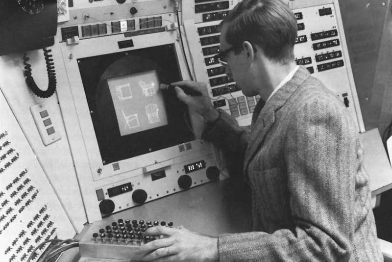
CAD and CAM emerged around the same time. In fact, the initial developments that would be crucial to the development of both CAD and CAM resulted from research work at MIT. For instance, the formal introduction of the first NC machine was held at MIT in 1952. The development of the APT programming language resulted from work by the Computer Applications Group at MIT’s Servo Lab. On the CAD front, researchers and scientists at MIT developed technologies that formed the foundation for the first interactive 2D engineering design and drafting software, Sketchpad. Sketchpad was released in 1963. Thus, the history of CAM and the history of CAD are intertwined in this regard.
Moreover, the growth of both CAD and CAM came in the 1980s due to the introduction of engineering workstations. Little wonder, then, that a lot of CAM companies were founded during this decade (see the timeline visual above). In the 1990s, mid-range modeler software like SolidWorks, Inventor, and Solid Edge were released. Given that these software applications did not have built-in CAM, their existence supported the continued development of CAM add-on solutions. Therefore, it is accurate to say that the evolution of CAD supported developments in CAM, contributing to the industry’s maturity.
Challenges and Controversies in CAM
Challenges
Manufacturers face the following challenges when it comes to using CAM solutions in their production operations:
- CAM programming can be time-consuming and complex, regardless of the simplicity of the parts
- Programmers need long periods of training to become familiar with the systems and to increase their productivity
- Shortage of qualified machine operators and programmers
- CAM software sometimes delivers unoptimized toolpaths
Controversies in the CAM Industry
Over the past 10 to 15 years, large players in the CAM industry have been busy making acquisitions and completing mergers. Following a series of acquisitions (see the visual below), Hexagon AB bought Vero Software, which owned multiple well-known CAM brands: AlphaCAM, EdgeCAM, Visi, SurfCAM, WorkNC, and more. It is worth pointing out that Vero came to own most of these products following mergers and acquisitions completed in the 2000s.
In 2020, Hexagon AB would then go on to acquire DP Technology Inc., the developer of the ESPRIT CAM system. That year, Battery Ventures acquired Cimatron and GibbsCAM from 3D Systems Inc. Like Vero Software, 3D Systems had acquired Cimatron Ltd. in 2015. Cimatron Ltd. had itself merged with Gibbs & Associates, the creator of GibbsCAM, in 2008.
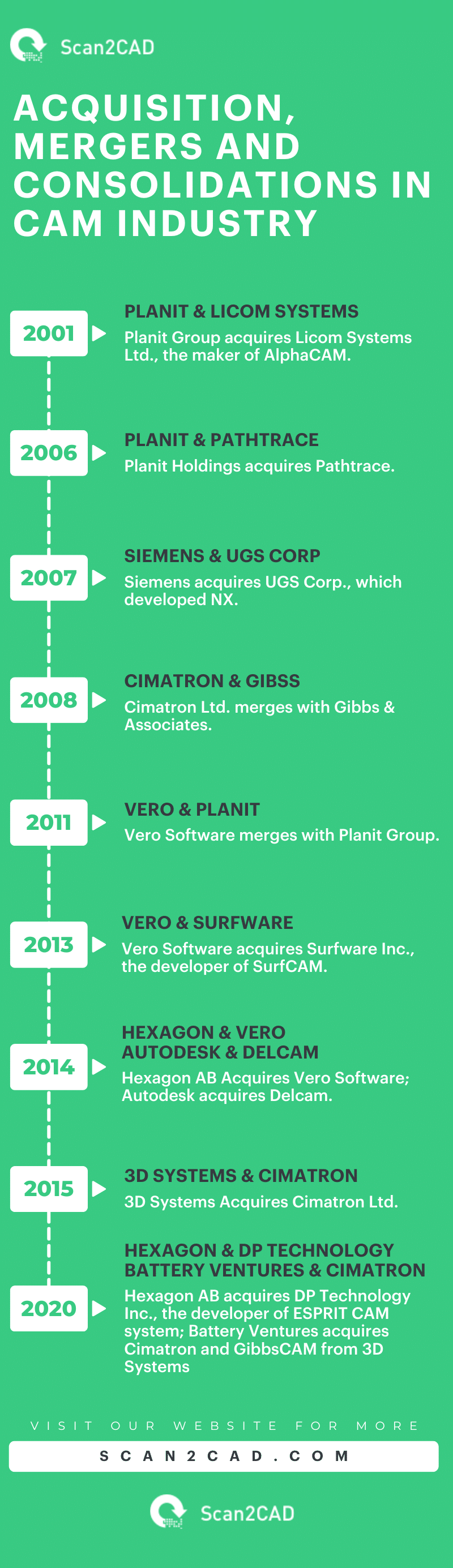
Infographic of Acquisitions, Mergers, and Consolidations in CAM Industry. Click to view full size.
M&As are not exactly a bad thing, as they help acquiring companies diversify operations, complement their existing product offerings, and increase their market share. However, consolidation can make customers feel as though the acquisitions will reduce the available choices and predispose them to the whims of the acquiring companies, especially if the companies opt to stop developing certain acquired software in favor of their original products.
Global Perspective of CAM Industry
Mordor Intelligence projects that the global CAM industry will grow at a compound annual growth rate (CAGR) of 8.13%, reaching $5.82 billion by 2030, up from $3.94 billion in 2024. The report expects North America to hold the highest market share, followed by Asia, with an equally high market share. Europe and Australia are expected to have medium adoption (hence market share), with low adoption in Africa, South America, and the Middle East.
Despite the low market share in some regions, the report demonstrates that manufacturers worldwide have adopted and integrated CAM solutions into their operations. As a result, CAM application developers have set up officers in multiple countries around the world and created distribution networks consisting of subsidiaries, resellers, integrators, and partners.
Moreover, CAM developers have been founded in different countries, a testament to the global demand for and proliferation of CAM. For instance, NTT Data Engineering Systems Corporation is a Japanese company that develops Space-E CAM, an intelligent CAD/CAM system, as well as Space-E CAA mold design add-on for CATIA V5. ZWSOFT, on the other hand, is a Chinese company that develops CAD/CAE/CAM software called ZW3D. HSMWorks Aps was a Denmark-based developer of a CAM add-on for SolidWorks; Autodesk acquired HSMWorks in 2012.
Emerging Technologies and Innovations in Present-Day CAM
Artificial Intelligence
Artificial intelligence (AI) is increasingly entering various markets, changing how jobs and tasks are traditionally done. AI is poised to continue to make its mark in the CAM industry. The most common areas where AI in CAM is used – and will continue to be used – include predictive maintenance, material optimization, production planning, and quality control.
On the quality control front, AI is used to identify errors in toolpaths that could lead to waste as well as anomalies and defects in products. Beyond simply identifying such errors, AI in CAM can potentially optimize the toolpaths to yield better results. AI can also be used to monitor machines’ operations and predict the exact time they will require maintenance. This is known as predictive maintenance.
Furthermore, AI models can be trained on how well to optimize the use of materials in manufacturing processes, thus improving efficiency and reducing waste. What’s more, AI can be deployed to optimize energy consumption and bolster sustainability thanks to its role in improving manufacturing efficiency.
Augmented Reality and Virtual Reality
Augmented reality (AR) and virtual reality (VR) enable design and manufacturing professionals to interact with drawings way before they are machined. This interaction allows them to easily identify and correct mistakes before the part is manufactured. At present, AR and VR solutions are still evolving. But we expect that as these technologies mature, their contribution to the world of manufacturing, particularly as regards their integration with CAM software, will increase.
Cloud-based CAM
Manufacturing thrives in collaboration between teams. No single department within a manufacturing organization can purport to work in isolation. Thus, to promote collaboration among teams, cloud-based CAM is slowly taking preeminence. In 2013, following the HSMWorks acquisition, Autodesk launched CAM 360. CAM 360 was designed to enable engineers and designers to download designs and digital prototypes from a web-based shared database and then prepare CNC machining programs. This solution was built on Autodesk’s existing cloud-based offerings, including Fusion 360.
In 2018, application developers Onshape and MecSoft launched the public beta for a browser-based CAM software called VisualCAMc. VisualCAMc was designed as the production CAM app for the web-based Onshape software.
Cloud-based CAM offers numerous advantages. For instance, it enables users to directly access cutting tool product datastored on a shared web-based database. In this regard, it reduces the time associated with obtaining such information, which is needed for accurate programming and simulation. It also enables users to access and open files stored in a remote database. Additionally, cloud-based CAM allows users to utilize the unlimited computing power of powerful data center computers.
Industrial Internet of Things (IIoT)
Industrial Internet of Things (IoT) involves the use of IoT devices and smart machines in manufacturing. To thrive, IIoT uses sensors that gather real-time data to support the automation, monitoring, and regulation of production procedures and operations. CAM can benefit from this real-time data. For example, IoT sensors can gather and deliver information such as machine performance and tool wear, allowing CAM software to adjust the machining programs according to the new information.
The Future of CAM
At this moment in time, CAM and CNC machines are readily available to the entire maker community. It’s easy enough to purchase CNC starter kits or even build your own CNC machine. So where exactly will CAM go in the future?
AI in Computer-Aided Manufacturing
Much like CAD, it’s clear that CAM is going to have to adapt with the times. Engineers and manufacturers will most definitely be looking for more ways to increase efficiency, minimize waste and reduce overall energy consumption. As with generative design in CAD, another hope in the maker community is that soon enough, CAM will be able to do far more and enable users to do far less. Essentially, machinists and CNC programmers will be able to take a step back. AI will be responsible for bringing about this level of automation.
Rise of CAD/CAM Systems
With the integration of CAD and CAM, we might also start to see a merging of roles in industries. The divide between engineers and machinists for example, might lessen. One thing’s for sure, as CAD/CAM software becomes more intuitive, designing will become far more advanced. Designs thought to be too difficult to attempt previously will eventually become child’s play.
CAM Influence on Education
In 2017, MIT introduced a manufacturing summer course. Developed by two professors, the course was a response to the changes in the world of manufacturing. It was intended to introduce students to the latest trends and technologies in CAM and manufacturing. Universities are taking note as new manufacturing technologies like robotics, 3D printing, nano-scale device capabilities (including micro-machining), and more transform what can be manufactured. Thus, learning institutions are poised to continue creating courses that respond to emerging market needs. They are also expected to partner with CAM application developers to better prepare their students for the workforce.
Changing Skill Sets
AI has given rise to the need to develop new skills. For instance, generative AI has birthed and magnified the skill of prompt engineering. AI in CAM is also poised to change how people approach manufacturing design software. Experts predict that with AI, designers and programmers will just need to specify the function instead of specifying and creating the object or assembly geometry by geometry, surface by surface, feature by feature, or part by part. The software will then perform the design task.
Here at Scan2CAD, we’re certainly looking forward to seeing where CAM goes next!
Interested in creating your own CNC projects? Use Scan2CAD to convert your CAD designs to G-code. Try out our free 14-day trial with no limitations or obligations! Alternatively, take a look at our free DXF designs!
