Improving raster conversion accuracy
About the Image Inspection Results
When converting a raster image Scan2CAD will first inspect the image to find any potential problems which could cause a less accurate conversion.
The image inspection begins whenever you start a vectorization and/or OCR by clicking the ‘Run’ button on the Vectorization Settings dialog.
What to do when your image has failed an Image Inspection
You will only see the Image Inspection Results dialog if your raster image has failed one or more of the checks.
Scan2CAD will list the problems that it has found with the image.
In the majority of cases you should fix the issues before continuing to the conversion.
Remember: Whatever exists in the image will be converted to vector. Therefore cleaning an image is always beneficial if you want to achieve the best conversion results.
| Result | Recommendation |
|---|---|
| This image has n colors. Consider reducing them. | The fewer the colors, the better the expected conversion results. In most cases an image can be represented as 2 colors; black and white (monochrome). You can reduce your image to black and white using the ‘Threshold’ tool in Raster Effects. If you need extra colors you can use the ‘Segment’ tool to reduce the colors. |
| This image contains n speckles. Consider removing them. | Speckles are small clusters of black pixels. These are typical in low quality images. Use the ‘Remove Speckles’ tool in Raster Effects to reduce the speckles. Please note: this number could include ‘false positives’ for example a ‘.’ text character could be identified as a speckle. Keep this in mind when removing speckles. |
| This image contains n holes. Consider removing them. | Holes are the opposite to speckles. They are clusters of white pixels encapsulated in colored areas. These are typical in low quality images. Use the ‘Remove Holes’ tool in Raster Effects to reduce the holes. Please note: this number could include ‘false positives’ for example the center part of an ‘o’ text character could be identified as a hole. Keep this in mind when removing holes. |
Choosing the correct raster line width
In this video we show how changing the ‘raster line width’ value can provide center-line or ‘outline’ tracing of raster lines in your drawings.
Is Your Raster Image Suitable For Vectorization?
Raster Quality Checklist for raster to vector conversion
The most common reason for poor raster to vector conversion results is an unsuitable raster image.
Scan2CAD can only give results as good as the raster image you give it to vectorize. Nowhere is the saying “Garbage In, Garbage Out” truer than in raster to vector conversion!
To make sure that your image is suitable for raster to vector conversion, go through the Raster Quality Checklist below.
Do this even if your scanned image looks perfect when viewed full screen. Poor quality raster images often look fine when viewed full screen – it’s only when you zoom in that you can see there’s a problem.
Alternatively, work through Andrea’s Real World Guide to Vectorization, a PDF document written by Softcover’s Andrea Tribe. Andrea has used Scan2CAD to vectorize hundreds of images of different types and quality. The Real World Guide tells you how to handle less than perfect scans and how to tweak vectorization settings. It will help you to get the best possible vectorization from any vectorizable image.
The Real World Guide can be accessed by going to Scan2CAD’s Help Menu, then selecting Real World Guide.
Is your image negative (white lines on a black background)?
Negative Image
Positive Image

Negative images should be made positive before raster to vector conversion Positive image
Scan2CAD converts positive images (black or coloured lines on white paper).If your image is negative you need to click ![]() (Negate) to convert it to positive.
(Negate) to convert it to positive.
Is your image skew?
Skew image
After deskew


Skewed images should be deskewed before raster to vector conversion After deskew
If your image is slightly skew, deskew it by clicking ![]() (Auto Deskew – black and white images only) or
(Auto Deskew – black and white images only) or ![]() (Rotate by Line – any image).
(Rotate by Line – any image).
Deskewing a very skew image can cause significant deterioration in image quality. If your image is very skew, the best thing to do is to rescan your drawing taking care to get the drawing straight on the scanner.
Is your image dirty?
If your image is very dirty, you may not be able to clean it well enough to produce a meaningful vectorization or cleaning it might take too long to be worthwhile.
For example, there is no point trying to clean an image that looks like the one below because there are solid black dirty areas obscuring the drawing.

However if speckles and dirty areas do not interfere with the drawing itself you will be able to clean the image quickly and easily.
To despeckle an image, click ![]() (Remove Speckles).
(Remove Speckles).
You can erase dirty areas using Scan2CAD’s raster erase tools, particularly the rectangular area erase (select ![]() ) and the irregular area erase (select
) and the irregular area erase (select ![]() ).
).
There are often dirty areas around the edges of raster images. You can delete these by cropping the image using Raster Effects > Crop.
Now, zoom into your raster image…
Zoom into your raster image by placing your cursor over the image and pressing M on your keyboard. Keep pressing M until the lines are highly magnified. You can also zoom in by scrolling your mouse wheel forwards.
What do you see?
Good quality lines

The lines above are clean and strong and distinct. If the lines on your image look like this you will be able to get good raster to vector conversion results.
Hairy lines

If the lines on your image have “hairs” like the top line above, click(Smooth) to smooth them (bottom line above).
Dithered lines

If the lines on your image are dithered (made up of black speckles like the lines above), the best thing to do is to rescan your drawing. Experiment with your scanner’s settings until you get a scan that has solid, continuous lines and is not dithered.
If rescanning is not an option, try using ![]() (Thicken Pixels).
(Thicken Pixels).
You may need to use Thicken Pixels several times to improve the quality of a dithered image to the point where it can be vectorized successfully. However, Thicken Pixels should be used with care as it can deteriorate the quality of the image by thickening lines too much and allowing lines that are close to each other to become joined.
Lines with holes

If the lines on your image contain small holes you can remove them using(Remove Holes). To remove large holes use Scan2CAD’s Flood Fill command (see the Scan2CAD Help).
If your image has holes it may have been scanned at too high a resolution. You may want to try scanning your drawing again at a lower resolution.
Broken lines
Raster to vector conversion cannot convert lines that are not there If the lines on your image are slightly broken you may be able to mend them automatically using one of or a combination of the following methods:
-
 (Thicken Lines).
 -
 (Thicken Pixels).
 -
Gap jumping. Before you vectorize the image:
- Select a Type from the Type Menu.
- Go to Type > Settings.
- Set a Gap Jump Distance.
When you vectorize the image Scan2CAD will jump over breaks that are smaller than the distance you have specified, allowing it to produce continuous vectors despite the gaps.
If the lines on your image are very broken you will not be able to mend them automatically or jump over the gaps using gap jumping. The only way to mend a very broken image is to draw new raster lines and arcs over the broken ones.
If your entire image is very broken it will take too long to improve its quality to the point where it can be successfully vectorized and there is probably no point trying. Your best bet is to rescan the drawing using our Scanning Checklist.
Small details
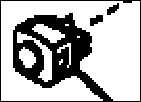
An image that has been scanned at a resolution that is optimal for most of the drawing may contain some small details that are made up of too few pixels to be sufficiently defined for raster to vector conversion.
Such details will vectorize to a mess of vectors. There is nothing you can do about this.
Dot and other non linear hatch patterns
Dot-type hatch patterns like the one in the drawing below will not vectorize well.

It is better to replace hatches like these in your CAD program than to try to vectorize them. If your drawing contains dot-type hatch patterns, remove them by clicking
![]() (Remove Speckles).
(Remove Speckles).
Hatch patterns like the one below where non-linear hatch components are joined to each other and to the surrounding boundary cannot easily be removed and will vectorize to a mess of vectors.

There is nothing you can do about this.
Touching parallel or concentric entities

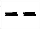
You will not get a good vectorization on parts of the image where parallel or concentric entities touch.
There is nothing you can do about this except rescan the drawing using our Scanning Checklist.
Merged entities
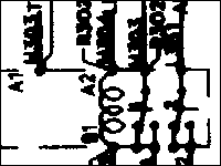
If the entities on your raster image are merged together the raster image is too poor quality for vectorization.
There is nothing you can do about this except rescan the drawing using our Scanning Checklist.
Blurry lines

If the lines on your raster image are blurry as in the image above, the raster image is too poor quality for vectorization.
There is nothing you can do about this except rescan the drawing using our Scanning Checklist.
Blurriness is most common in JPEG images, so take care not to save your image in JPEG format.
Low resolution lines
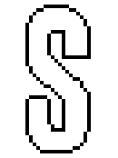
If shapes in your image are defined by only a few pixels and look jagged, as in the image above, your image is too low resolution. This is particularly common in logos and drawings that contain fine detail.
The drawing needs to be rescanned at a considerably higher resolution – aim for lines that are about 5 pixels thick.
Overlaid information


The drawings above contain a lot of overlaid information.
Unfortunately, Scan2CAD is not human. It doesn’t know that it is looking at (for example) text and a wiring schedule overlaid on a building plan. All it sees are black patterns on a white background and it is not going to be able to unscramble the different components.
You are not going to get a sensible raster to vector conversion from an image with overlaid information. There is nothing you can do about this.
Is The Text On Your Raster Image Suitable For OCR Text Recognition?
Raster Text Quality Check-list for OCR text recognition
Scan2CAD has a capability for converting raster text to vector text using OCR. When you convert raster text using OCR, the vector text is proper editable text rather than a series of uneditable lines and arcs.
Scan2CAD’s OCR recognizes raster text where the following conditions are met:
- The raster text is easily legible.
- The raster text characters do not touch each other.
- The raster text characters do not touch other drawing elements.
- The raster text characters are not at different orientations.
- The raster text characters are in a font that Scan2CAD can recognize.
To ensure that your text meets these conditions, work through the following Raster Text Quality Checklist.
First, place your cursor over a piece of text on your image. Press M to Magnify. Press M again and again until your image is highly magnified. Or, zoom in by scrolling your mouse wheel forward. To zoom out again, click ![]() .
.
Is the text easily legible?
If you cannot read the text easily, as in the examples below, Scan2CAD won’t be able to read it either.
If the text is not easily legible, the only remedy is to start off with a better quality raster image.
If this is not possible, you will have to retype the text manually. You can either do this in Scan2CAD or in your CAD program after you have imported the converted file into it.
You may want to erase areas of very poor quality text from the raster image so that these areas are not vectorized to lines and arcs.
### Are the characters touching?
Scan2CAD cannot recognize characters that touch other characters, even if the characters are only connected by a few pixels:

If the characters touch, try selecting OCR > Settings > Split before doing OCR recognition. When this option is selected Scan2CAD will attempt to split and identify touching characters.
This will improve text recognition on some raster images, however on others it may result in a lot of “junk characters” being recognized. This is because characters that touch are often very poor quality and are unrecognizable even after splitting. For example, the characters in the example above have “bled”. Not only has this caused them to touch each other but it has also filled in the “A”. This means that the “A” is no longer typical of an “A” and Scan2CAD may have difficulty recognizing it even if it is not touching other characters.
You can often improve the quality of an image that has bled by rescanning it in grayscale and thresholding it (see the Scanning Checklist).
Is the text written over other drawing elements?
If text is written over drawing elements or is attached to underlining or boxes as in the examples below, Scan2CAD won’t be able to recognize it.
Is the text at more than one orientation?

Where text at one orientation is intermingled with text at another orientation it is virtually impossible to recognize all the text.
Can Scan2CAD recognize the font?
By default, Scan2CAD can only recognize text that has been written using a standard font such as the font in the example below.

It may not recognize other fonts well. It may also fail to recognize standard fonts that are narrower or wider than normal or that are italicized.
If Scan2CAD’s default text recognition cannot recognize a font well and you have a lot of images containing that font, you can train Scan2CAD to recognize the font (Pro version only). You can do this if the font characters are consistent and do not touch. For example:

Scan2CAD’s default text recognition will recognize this font but it will not recognize it optimally because the font is narrower than normal. You could train Scan2CAD to recognize this font well.

Scan2CAD’s default text recognition will recognize this font very poorly because it is italicized and hand written. However, because the characters are clear and do not touch you could train Scan2CAD to recognize it.

Scan2CAD’s default text recognition will recognize this font very poorly because it is hand written and because the characters touch each other. You could not train Scan2CAD to recognize this font because the characters touch.

Despite the fact that the quality of this text is poor you could train Scan2CAD to recognize it because the characters are consistent and do not touch each other.
It takes a few hours to train Scan2CAD to recognize a font but it can significantly improve text recognition.
Scanning A Drawing For Optimal Raster To Vector Conversion Results
How to scan a drawing for raster to vector conversion
Not all drawings can be scanned to create a raster image that can be used for raster to vector conversion. For example:
- Some drawings are so faint or so dirty that whatever you do you will not be able to create a clean enough scan for conversion.
- Some drawings or drawing details are too small to scan well enough for vectorization, regardless of the scanning resolution you use.
- Some drawings contain so many overlapping details – for example text written over drawing lines – that even if you get a perfect scan no raster to vector converter will be able to unscramble the information.
However, given a suitable drawing in good enough condition to scan well, you can eliminate many raster to vector conversion problems by being aware of the information on this page.
Color, grayscale or monochrome?
Most scanners give you the option of scanning in color, grayscale or monochrome. These options have different names depending on the make of scanner you have.
Color
Your scanner’s color option will normally create a raster image that contains 16.7 million colors.
You should only use this option if you are scanning a color drawing with a view to converting it to a color DXF file. Do not use your scanner’s color option if you are scanning a black and white drawing – it is easy to do this by accident as most scanners default to color.
If you are scanning a color drawing with a view to converting it to a color DXF file, experiment with your scanner’s settings until the colors on the raster image are as high contrast, vibrant and saturated as possible.
Warning: Color images can be very large. An E/A0 size drawing scanned in color at 300 dpi will take up about 385Mb of memory.
Grayscale
Your scanner’s grayscale option (often called black and white photo) will normally create an image that contains 256 shades of gray.
Grayscale images are not normally suitable for raster to vector conversion. You should only select grayscale if you are going to convert the grayscale image to black and white after scanning using Scan2CAD’s Threshold functions.
See the Scan2CAD Help for more information on Simple and Adaptive Thresholds.
Warning: Grayscale images can be very large. An E/A0 size drawing scanned in grayscale at 300 dpi will take up about 128Mb of memory.
Monochrome
Your scanner’s monochrome option (often called line art, black and white drawing or 1 bit) will create a much smaller image that contains two colors – black and white. This is the option you should normally choose when scanning a drawing for raster to vector conversion.
Thresholding
When you scan a drawing in monochrome your scanner or scanning software has to make a decision about which parts of the drawing to set to black in the raster image and which to set to white. This is called thresholding.
If your drawing is clean and sharp this is not normally a problem. However if your drawing has faint lines or a dirty or tinted background you will have to experiment with your scanner’s settings until you get a raster image where, as far as possible, the parts of the raster image that are supposed to be black are black and the parts that are supposed to be white are white.
If your scanner or scanning software sets too much of the drawing to white, it may contain breaks and holes and faint parts may be lost. If your scanner or scanning software sets too much of the drawing to black, text characters may “bleed” so that white spaces within them or between them become filled and speckles and dirt may appear in the background.
Too much white
Too much black


Optimal

While some scanners have good automatic thresholding and / or have software that makes setting an appropriate threshold easy, getting the best threshold on other scanners requires endless rescans.If this is the case with your scanner, you may find it easier to scan your drawing in grayscale. You can then use Scan2CAD’s Threshold functions to create a black and white image after scanning. This will allow you to experiment with different levels of black and white without having to rescan the drawing.
Resolution
It is not true that “the higher the scanner resolution, the better the vectorization results”. In fact, a high resolution scan can sometimes give you worse results than a low resolution scan!
That said, you should be aware that while you can decrease the resolution of an image after scanning you cannot increase it. Increasing resolution after scanning will not regain any lost detail. It will simply exacerbate “steps” in the image that will decrease the quality of any raster to vector conversion.
Therefore, it is better to err on the side of too high resolution rather than too low resolution when scanning. If you find your scan resolution is too high you can always decrease it after the fact using Scan2CAD’s File Menu > Raster > Statistics dialog.
For most drawings, a scan resolution of 200 to 400 dpi is optimal. However, if a drawing is small (e.g. a logo) or has fine detail, you may need a higher resolution.
Here are some pointers for choosing the right resolution:
- If you are scanning a line drawing aim for lines about 5 pixels thick.
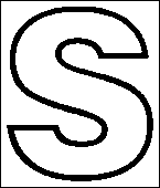
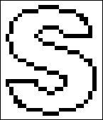
- Lines and outlines should look smooth, not stepped:
Smooth – GOOD
Stepped – BAD


- Text characters and entities that are close together should be separated by clean white space:
Completely separated – GOOD
Incompletely separated – BAD
Completely unseparated – BAD
Note that the separation of close together entities is dependent on selecting an appropriate threshold (see above) as well as on selecting an appropriate resolution.
Saving raster images
We recommend that you save your scanned drawings as TIFF files. If your scanned drawing is black and white, save it as a Group 4 TIFF file. This will compress the file without causing a loss in its quality.
Do not save your scans as multi layer/page TIFF files, which Scan2CAD does not support.
DO NOT save your images as JPEG. JPEG uses “lossy compression”, which means that it discards data it thinks you can do without. This causes it to decrease the quality of scanned drawings by blurring the details and adding speckle artifacts.
The smudging and gray “clouds” surrounding the lines in the image below are typical artifacts caused by saving a drawing as JPEG.

Once you have damaged an image by saving it as JPEG, you cannot undo the damage by simply converting the JPEG image to TIFF. You will need to rescan the drawing.
VERY IMPORTANT: CHECK YOUR SCAN!
After scanning, check your scan.
- Make sure that the full extents of the drawing have been captured.
- Make sure the scan is not skew.If the scan is skew, rescan the drawing straight. While Scan2CAD can deskew scans, deskewing can decrease the quality of the scan, particularly if the scan is very skew.
- Make sure that any text is legible.
- Make sure that text characters and entities that are close together are separated by clean white space.
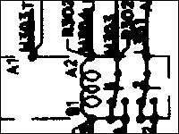
- If they touch partially or completely, you need to experiment with your threshold settings and or scanning resolution.
- Make sure that the drawing lines are solid, not broken.


If they are broken, you need to experiment with your threshold settings and or scanning resolution.