CNC is at the heart of today’s burgeoning maker movement. Using simple tools like CNC routers, milling machines and laser cutters, you could produce anything from laptop decals to wooden signs. In fact, you could start your own CNC project from your very own home. You don’t even have to learn how to code or design on CAD software! All you need is some clever image conversion software like Scan2CAD that will do all of the heavy-lifting for you. It will automatically convert your sketch or any image into a CNC-ready vector design!
How does image conversion work?
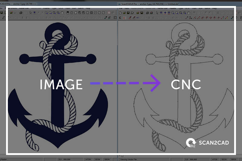
CNC machines work with vector cnc file formats, such as DXF and G-code files. Instead of drawing an image from scratch on CAD software, conversion software like Scan2CAD traces an image using intelligent vectorization algorithms. Then, it translates it into a CNC format using a language that can be read by any CNC software. i.e. a set of mathematical instructions known as vectors. These numbers are graphic coordinates that control the movement of your CNC cutter. For example, the CNC machine would carve a straight line by moving its cutter five units left, starting from point A. This image tracing technique can be applied onto any raster file type including BMP, PNG, TIFF, JPEG, GIF, PDF and so on. You could scan a sketch , convert a logo old technical drawing… the opportunities are endless! Even raster text can be converted to vector text.
Converting an image to DXF or G-code in Scan2CAD
What are the most common CNC file formats?
Most commonly, CNC software will utilise either DXF or G-code files for cutting. G-code files contain a direct set of instructions for the cutter where-as DXF files are more generic, they can contain data totally unrelated to CNC cutting such as text strings.
DXF files can be considered more flexible than G-code files because they are not the end-instructions for the CNC file. You can edit DXF files to achieve the required design and scaling before exporting the file to G-code. Once the file is in a CNC format (i.e. G-code) it can be more challenging to make edits.
G-code files do not have just one file extension. G-code files are typically represented with 3 file extensions:
- example.cnc
- example.nc
- example.tap
In all 3 cases, the contents of the CNC file are identical. The only difference is the file extension. Therefore if you need to convert a .nc file to a .tap file, you can simply change the file name’s extension.
How do I convert my image for CNC?
1. Load your image in Scan2CAD
Download the Scan2CAD free trial. Launch Scan2CAD and click: ‘File’ > ‘Open‘. Choose your image file.
2. Clean the image (optional)
If you have a low quality image, you can clean it using Scan2CAD’s image cleaning tools before converting to vector. This ensures that your CNC file format image is crisp and clear for your CNC machine. It’s a great option for cleaning a distorted or heavily compressed image.
3. Convert
Scan2CAD will convert your image to a CNC file format in seconds. Simply choose the ‘Convert Raster Image’ option and convert using the ‘Outline’ option. This will provide you with a clear and cut-friendly CNC profile of your original image.
4. Save the file in a CNC file format
Click the green ‘Export’ button in the upper-right corner of the software to export the file to your preferred CNC file format. The most widely compatible file format is the DXF file format. If in doubt, always choose DXF because every CAD/CAM/CNC software will support this open-sourced file format. Scan2CAD also allows you to save your vector into G-code formats such as NC, CNC and TAP.
That’s it. You’re all done! Now, you can now import the newly-created vector file in any CAM/CNC software and use it with any machine of your choice—here’s a rundown of our favourite beginners CNC kits.
How long does image conversion take?
The conversion process only takes 30 seconds and about ten clicks of your mouse. However, the quality of your output vector file depends on the quality of your image. Garbage in, garbage out. You have to choose the right image to begin with. Then, there’s a small amount of pre- and post-processing work you should do to obtain the best conversion possible, check out our top 10 raster effects for a better idea.
How do I make the image CNC-ready?
After conversion, your DXF file is only, at best, 95% cut ready. Once you load it onto the CAM program, you’ll have to assign cut paths, order the cut paths and select offsets for the cut paths. These settings vary depending on the type of CNC machine you’re using, speeds, amperage, pressures, etc.
Inside tips on image conversion for CNC
We spoke recently to Jason Henry, owner of Cascade Metal Designs LLC, who divulged his expert tips on image conversion for CNC.
- High resolution. You’ll want to be able to zoom into the image without any heavy pixelation. However, you don’t necessarily need your image to be scanned in HD either. The rule of thumb is that each line should be five pixels thick for ideal conversion.
- Does not contain shadows. Shadows prevent us from seeing the details of the design work, which can lead to problems when the image is being cut.
- An image file that uses lossless compression, such as PNG, BMP or TIFF. You should avoid JPEGs and GIFs, as some image details are compromised in exchange for small file size. For more information, check out our 33 supported file types, or learn how to convert BMP to DXF.
- “Clean” images without speckles, blurry sections and overlapping elements.
- As few colors as possible. For example, you should convert grayscale images into black and white before conversion.
- Contains just the right amount of detail. If there’s more detail than you need, erase it or increase threshold and contrast of the image.
Read this article to learn about choosing the right image for raster-to-vector conversion.
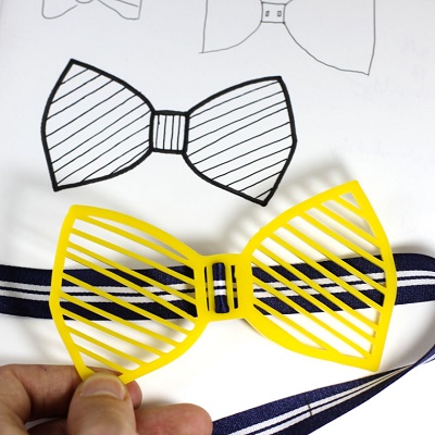
Fellow maker, Marcel doodled a bowtie in his notebook and converted it into actual accessory! Notice that he used a felt-tip pen so that the software can detect clear, clean outlines. Source: hotpopfactory.com/blog
- The vector uses single line cut paths to represent key features of the main silhouette. You can join multiple separate lines or polylines using Scan2CAD’s Snap tool.
- Remove as many intersections and node counts as you can, without sacrificing image quality.
- Ensure all lines are connected perfectly, so that you get one coherent cut path. Pay particular attention to this near corners and curves.
- No overlapping vectors.
- Any design work that you do not want to cut is deleted.

Example: The image on the left is much more suitable for conversion
For example, a plasma cutting system requires significantly larger cut paths than a more precise laser-cutting system. For plasma cutting systems and some routing systems, you would use open, single-line cut paths. In comparison, you would only use closed or looped cut paths with a laser and waterjet cutting system. The same logic applies if you’re cutting out a small-sized design. You have to sacrifice some detail and use single cut paths if you’re making small products; the converse is true if you’re making larger-sized items.
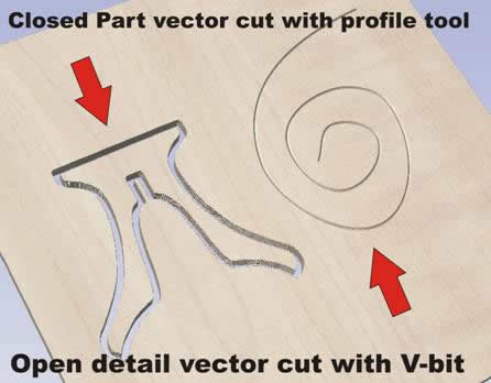
Closed cut paths can only be used with more precise CNC cutting machines. Source: makecnc.com
To learn more about CAD and milling strategies, check out this guide to Mastering CAD and CAM for CNC Machining by Michael Zalewski.
With a few clicks and some advice from experts, anyone can convert an image into a CNC project. For inspiration, check out our recent round-up of 32 Products You Could Make & Sell Today. Don’t forget to download Scan2CAD’s free trial too. Equipped with intelligent vectorization algorithms as well as a full raster and vector image editing suite, it’s got all the tools you need for your CNC project.
